Carregar apresentação
A apresentação está carregando. Por favor, espere

1
Estrutura da Matéria

2
História Até meados do século XIX, o que se conhecia acerca dos materiais era essencialmente empírico, ou na melhor das hipóteses, resultado de alquimia. Com o desenvolvimento do microscópio eletrônico no inicio de século XX, um grande salto no conhecimento dos materiais foi dado. A observação ao microscópio, permitiu estudos sistemáticos, que por sua vez conduziram ao domínio dos materiais e de seus processos de fabricação e transformação, dando origem à Ciência dos Materiais e, posteriormente, à Engenharia de Materiais. Hoje, dispõe-se de aproximadamente materiais que compõem o cenário industrial moderno, classificado em cinco grandes grupos: os metais, as cerâmicas, os polímeros, os semicondutores e os compósitos.

3
Ementa e Objetivos Ementa:
Cristais: estruturas cristalinas (vidro e cerâmica, cristais líquidos). Materiais isolantes e condutores (supercondutores, termo-elementos, efeito Peltier). Materiais dielétricos (condensadores). Materiais piezoelétricos. Introdução à Física do Estado Sólido: Bandas de energia. Fisica de Semiconducores. Juncões PN. Objetivos Permitir ao futuro Engenheiro de Computação entender os fenômenos que dão origem ao funcionamento de dispositivos semicondutores de forma a auxilia-lo no entendimento de futuras tecnologias na área de dispositivos eletrônicos, auxiliar em sua função de coordenar projetos de sistemas de computação e fornecer alguma flexibilidade a sua formação acadêmica.
. Materiais isolantes e condutores (supercondutores, termo-elementos, efeito Peltier). Materiais dielétricos (condensadores). Materiais piezoelétricos. Introdução à Física do Estado Sólido: Bandas de energia. Fisica de Semiconducores. Juncões PN. Objetivos. Permitir ao futuro Engenheiro de Computação entender os fenômenos que dão origem ao funcionamento de dispositivos semicondutores de forma a auxilia-lo no entendimento de futuras tecnologias na área de dispositivos eletrônicos, auxiliar em sua função de coordenar projetos de sistemas de computação e fornecer alguma flexibilidade a sua formação acadêmica.")
4
Plano de Aulas 02/03 - Cristalografia. 18/06 - Semicondutores
16/06 - Diodos 30/03 – Introdução à quantica 23/06 - Diodos 30/07 - Diodos 07/05 - 06/08 - PROVA 2. 14/05 - Quantica 21/05 - Quantica 28/05 - Quantica 04/06 - Quantica 07/06 -PROVA 1. 11/06 - Semicondutores

5
Estruturas Cristalinas.
1.1.1 Classificação dos Materiais. 1.1.2 Estrutura Atômica e Ligações Interatomicas. 1.1.3 Redes Cristalinas.

6
Estrutura dos Materiais
Tipos de Materiais Ligações Químicas Redes Cristalinas

7
Ciência dos Materiais Investigação das relações que existem entre as estruturas da matéria e suas propriedades. Estrutura Sub-atômica Estrutura Atômica Estrutura Microscópica Estrutura Macroscópica Elétrons e núcleos Organização de átomos ou moléculas Aglomeração de átomos >> Estrutura Atômica Matéria Visível Ciência dos Materiais - CEUNES 7 7

8
Relação Estrutura x Propriedades
As propriedades “cotidianas” dos materiais dependem da estrutura em escala atômica - nanoestrutura da microestrutura (estrutura em escala intermediária) Alumínio (estrutura cúbica) Magnésio (estrutura hexagonal) Fibras de vidro em uma matriz de polímero. 50 µm Ambos são metais mas o Al é mais dúctil devido à estrutura cúbica Ciência dos Materiais - CEUNES 8
 Alumínio. (estrutura cúbica) Magnésio. (estrutura hexagonal) Fibras de vidro em uma matriz de polímero. 50 µm. Ambos são metais mas o Al é mais dúctil devido à estrutura cúbica. Ciência dos Materiais - CEUNES. 8.")
9
Classificação de Materiais
Metais Cerâmicas Polímeros Compósitos Semicondutores Biomateriais Ciência dos Materiais - CEUNES 9

10
Ciência dos Materiais - CEUNES
Metais Propriedades básicas Fortes e podem ser moldados Dúcteis (deformam antes de quebrar) Superfície “metálica”, não são transparentes à luz visível. Bons condutores de corrente elétrica e de calor Ciência dos Materiais - CEUNES 10
 Superfície metálica , não são transparentes à luz visível. Bons condutores de corrente elétrica e de calor. Ciência dos Materiais - CEUNES. 10.")
11
Os metais na tabela periódica
Ciência dos Materiais - CEUNES 11

12
Ciência dos Materiais - CEUNES
Cerâmicas e vidros Propriedades básicas São uma combinação de metais com O, N, C, P, S São altamente resistentes a temperatura (refratários) São isolantes térmicos e elétricos São frágeis (quebram sem deformar) São menos densas do que metais Podem ser transparentes Ciência dos Materiais - CEUNES 12
 São isolantes térmicos e elétricos. São frágeis (quebram sem deformar) São menos densas do que metais. Podem ser transparentes. Ciência dos Materiais - CEUNES. 12.")
13
As Cerâmicas na tabela periódica
Si e Ge são semicondutores mas são usados em cerâmicas de forma equivalente a metais Ciência dos Materiais - CEUNES 13

14
Ciência dos Materiais - CEUNES
Polímeros Propriedades básicas São sintéticos Altamente moldáveis - plásticos São formados pela combinação de “meros” São formados por um número bem limitado de elementos. C e H, O (acrílicos), N (nylons), F (fluor-plásticos) e Si (silicones). São leves e não frágeis Em geral são menos resistentes do que metais e cerâmicas Ciência dos Materiais - CEUNES 14
, N (nylons), F (fluor-plásticos) e Si (silicones). São leves e não frágeis. Em geral são menos resistentes do que metais e cerâmicas. Ciência dos Materiais - CEUNES. 14.")
15
Os Polimeros na tabela periódica
Ciência dos Materiais - CEUNES 15

16
Ciência dos Materiais - CEUNES
Compósitos O que são ? Combinação de metais, cerâmicas e polímeros Preservam as propriedades “boas” dos componentes e possuem propriedades superiores às de cada componente separado. Fibra de Vidro Ciência dos Materiais - CEUNES 16

17
Ciência dos Materiais - CEUNES
Semicondutores Propriedades básicas Condutividade finamente controlada pela presença de impurezas - dopantes. Podem ser combinados entre si para gerar propriedades eletrônicas e óticas “sob medida”. São a base da tecnologia de opto-eletrônica-lasers, detetores, circuitos integrados óticos e células solares. Todos os componentes eletrônicos do computador Ciência dos Materiais - CEUNES 17

18
Os Semicondutores na tabela periódica
Quando combinados entre si (coluna 3A-5A e 2B-6A) os metais (em amarelo) assumem propriedades semicondutoras. Ciência dos Materiais - CEUNES 18
 os metais (em amarelo) assumem propriedades semicondutoras. Ciência dos Materiais - CEUNES. 18.")
19
Ciência dos Materiais - CEUNES
Biomateriais Propriedades básicas Materiais utilizados na area da saude para ajudar o ser humano. Usado em medicina na substituição de partes do corpo humano. Ciência dos Materiais - CEUNES 19

20
Ciência dos Materiais - CEUNES
Seleção de Materiais Ex: Cilindro de armazenamento de gases Requerimento: resistir a altas pressões (14MPa) Resistência Flexibilidade Custo Metais Cerâmicas Polímeros Semicondutores Compósitos Ciência dos Materiais - CEUNES 20
 Resistência. Flexibilidade. Custo. Metais. Cerâmicas. Polímeros. Semicondutores. Compósitos. Ciência dos Materiais - CEUNES. 20.")
21
Ciência dos Materiais - CEUNES
Seleção de Materiais Ex: Vaso de pressão de uma aeronave Requerimento: resistir a altas pressões e ser leve Aqui o custo é menos importante do que a funcionalidade Prefere-se um material leve e forte, mesmo sendo caro. Resistência Flexibilidade Custo Metais Cerâmicas Polímeros Semicondutores Compósitos Ciência dos Materiais - CEUNES 21

22
Ligações Químicas – Primeira Aproximação.
IONIC BONDING

23
Ligações Químicas – Primeira Aproximação.
IONIC BONDING

24
The attractive bonding forces are coulombic; that is, positive and negative ions,
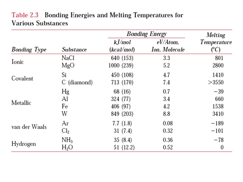
by virtue of their net electrical charge, attract one another. For two isolated ions, the attractive energy EA is a function of the interatomic distance according to (2.8) An analogous equation for the repulsive energy is (2.9) In these expressions,A,B, and n are constants whose values depend on the particular ionic system. The value of n is approximately 8. Ionic bonding is termed nondirectional, that is, the magnitude of the bond is equal in all directions around an ion. It follows that for ionic materials to be stable, all positive ions must have as nearest neighbors negatively charged ions in a threedimensional scheme, and vice versa. The predominant bonding in ceramic materials is ionic. Some of the ion arrangements for these materials are discussed in Chapter 3. Bonding energies, which generally range between 600 and 1500 kJ/mol (3 and 8 eV/atom), are relatively large, as reflected in high melting temperatures.
 An analogous equation for the repulsive energy is. (2.9) In these expressions,A,B, and n are constants whose values depend on the particular ionic system. The value of n is approximately 8. Ionic bonding is termed nondirectional, that is, the magnitude of the bond is equal in all directions around an ion. It follows that for ionic materials to be stable, all positive ions must have as nearest neighbors negatively charged ions in a threedimensional scheme, and vice versa. The predominant bonding in ceramic materials is ionic. Some of the ion arrangements for these materials are discussed in Chapter 3. Bonding energies, which generally range between 600 and 1500 kJ/mol (3 and. 8 eV/atom), are relatively large, as reflected in high melting temperatures.")
25
COVALENT BONDING

26
COVALENT BONDING In covalent bonding stable electron configurations are assumed by the sharing of electrons between adjacent atoms. Two atoms that are covalently bonded will each contribute at least one electron to the bond, and the shared electrons may be considered to belong to both atoms. The covalent bond is directional; that is, it is between specific atoms and may exist only in the direction between one atom and another that participates in the electron sharing.

27
COVALENT BONDING The number of covalent bonds that is possible for a particular atom is determined by the number of valence electrons. For N valence electrons, an atom can covalently bond with at most 8 N other atoms. For example, N 7 for chlorine, and 8 N 1, which means that one Cl atom can bond to only one other atom, as in Cl2 . Similarly, for carbon, N 4, and each carbon atom has 8 4, or four, electrons to share. Diamond is simply the three-dimensional interconnecting structure wherein each carbon atom covalently bonds with four other carbon atoms. Covalent bonds may be very strong, as in diamond, which is very hard and has a very high melting temperature, 3550C (6400F), or they may be very weak, as with bismuth, which melts at about 270C (518F). It is possible to have interatomic bonds that are partially ionic and partially covalent, and, in fact, very few compounds exhibit pure ionic or covalent bonding. For a compound, the degree of either bond type depends on the relative positions of the constituent atoms in the periodic table (Figure 2.6) or the difference in their electronegativities (Figure 2.7). The wider the separation (both horizontally relative to Group IVA—and vertically) from the lower left to the upper-right-hand corner (i.e., the greater the difference in electronegativity), the more ionic the bond. Conversely, the closer the atoms are together (i.e., the smaller the difference in electronegativity), the greater the degree of covalency.
, or they may be very weak, as with bismuth, which melts at about 270C (518F). It is possible to have interatomic bonds that are partially ionic and partially covalent, and, in fact, very few compounds exhibit pure ionic or covalent bonding. For a compound, the degree of either bond type depends on the relative positions of the constituent atoms in the periodic table (Figure 2.6) or the difference in their electronegativities (Figure 2.7). The wider the separation (both horizontally relative to Group IVA—and vertically) from the lower left to the upper-right-hand corner (i.e., the greater the difference in electronegativity), the more ionic the bond. Conversely, the closer the atoms are together (i.e., the smaller the difference in electronegativity), the greater the degree of covalency.")
29
METALLIC BONDING

30
METALLIC BONDING Metallic bonding, the final primary bonding type, is found in metals and their alloys. A relatively simple model has been proposed that very nearly approximates the bonding scheme. Metallic materials have one, two, or at most, three valence electrons. With this model, these valence electrons are not bound to any particular atom in the solid and are more or less free to drift throughout the entire metal. They may be thought of as belonging to the metal as a whole, or forming a ‘‘sea of electrons’’ or an ‘‘electron cloud.’’

31
Metallic Bonding

32
Metallic Bonding The free electrons shield the positively charged ion cores from mutually repulsive electrostatic forces, which they would otherwise exert upon one another; consequently the metallic bond is nondirectional in character. In addition, these free electrons act as a ‘‘glue’’ to hold the ion cores together. Bonding energies and melting temperatures for several metals are listed in Table 2.3. Bonding may be weak or strong; energies range from 68 kJ/mol (0.7 eV/atom) for mercury to 850 kJ/mol (8.8 eV/atom) for tungsten. Their respective melting temperatures are 39 and 3410C (38 and 6170F). Metallic bonding is found for Group IA and IIA elements in the periodic table, and, in fact, for all elemental metals.
 for mercury to 850 kJ/mol (8.8 eV/atom) for tungsten. Their respective melting temperatures are 39 and 3410C (38 and 6170F). Metallic bonding is found for Group IA and IIA elements in the periodic table, and, in fact, for all elemental metals.")
33
SECONDARY BONDING OR VAN DER WAALS BONDING
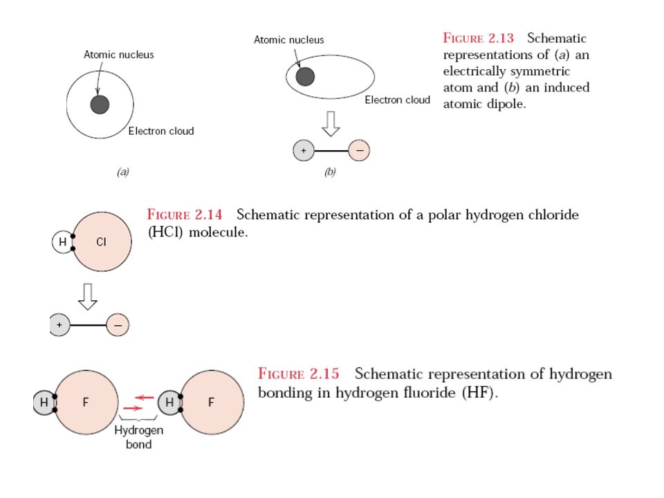
Secondary, van der Waals, or physical bonds are weak in comparison to the primary or chemical ones; bonding energies are typically on the order of only 10 kJ/mol (0.1 eV/atom). Secondary bonding exists between virtually all atoms or molecules, but its presence may be obscured if any of the three primary bonding types is present. Secondary bonding forces arise from atomic or molecular dipoles. In essence, an electric dipole exists whenever there is some separation of positive and negative portions of an atom or molecule. Hydrogen bonding, a special type of secondary bonding, is found to exist between some molecules that have hydrogen as one of the constituents.
. Secondary bonding exists between virtually all atoms or molecules, but its presence may be obscured if any of the three primary bonding types is present. Secondary bonding forces arise from atomic or molecular dipoles. In essence, an electric dipole exists whenever there is some separation of positive and negative portions of an atom or molecule. Hydrogen bonding, a special type of secondary bonding, is found to exist between some molecules that have hydrogen as one of the constituents.")
36
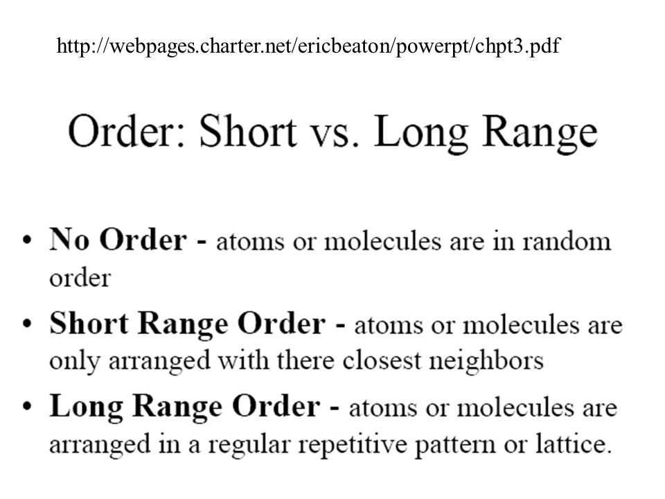
Estruturas dos sólidos
Formas com que os átomos se organizam: Molecular Cristalina Vítrea

38
Sólidos Cristalinos When describing crystalline structures, atoms (or ions) are thought of as being solid spheres having well-defined diameters. This is termed the atomic hard sphere model in which spheres representing nearest-neighbor atoms touch one another. An example of the hard sphere model for the atomic arrangement found in some of the common elemental metals is displayed in Figure 3.1c.
 are thought of as being solid spheres having well-defined diameters. This is termed the atomic hard sphere model in which spheres representing nearest-neighbor atoms touch one another. An example of the hard sphere model for the atomic arrangement found in some of the common elemental metals is displayed in Figure 3.1c.")
39
Sólidos moleculares • Deformação moléculas deslizam (tp) Molécula
Sólidos moleculares • Deformação moléculas deslizam (tp) moléculas rompem (tf) • Exemplo: Betumes e alguns plásticos • Podem ser cristalinos (tp) vítreos (tp ou tf) Molécula Grupos de átomos c/ forte ligação • Sólido moléculas c/ ligação fraca depende do GP
 moléculas rompem (tf) • Exemplo: Betumes e alguns. plásticos. • Podem ser. cristalinos (tp) vítreos (tp ou tf) Molécula. Grupos de átomos c/ forte. ligação. • Sólido. moléculas c/ ligação fraca. depende do GP.")
40
Sólidos Cristalinos • Metais • Ordem • Iônicos ou covalentes
• Alto ponto de fusão • Resistentes • Duros • Ordem • Simetria • Repetição • Estáveis • Planos de clivagem • Anisotrópicos

41
Sólidos Cristalinos • Centro de simetria • Eixo(s) de simetria
• Plano de simetria Mais detalhes • Empacotamento dos átomos: Volume dos átomos na unidade de volume da célula Volume da célula

42
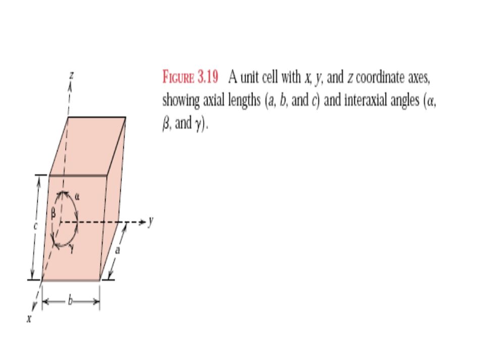
The atomic order in crystalline solids indicates that small groups of atoms form a repetitive pattern. Thus, in describing crystal structures, it is often convenient to subdivide the structure into small repeat entities called unit cells. Unit cells for most crystal structures are parallelepipeds or prisms having three sets of parallel faces; one is drawn within the aggregate of spheres (Figure 3.1c), which in this case happens to be a cube. A unit cell is chosen to represent the symmetry of the crystal structure, wherein all the atom positions in the crystal may be generated by translations of the unit cell integral distances along each of its edges. Thus, the unit cell is the basic structural unit or building block of the crystal structure and defines the crystal structure by virtue of its geometry and the atom positions within. Convenience usually dictates that parallelepiped corners coincide with centers of the hard sphere atoms. Furthermore, more than a single unit cell may be chosen for a particular crystal structure; however, we generally use the unit cell having the highest level of geometrical symmetry. Normalmente representa-se uma rede pelas chamadas células convencionais, elas são mais fáceis de ser visualizadas mas não são necessariamente as menores que reproduzem a rede pela translação repetitiva. Estas são as células primitivas.

43
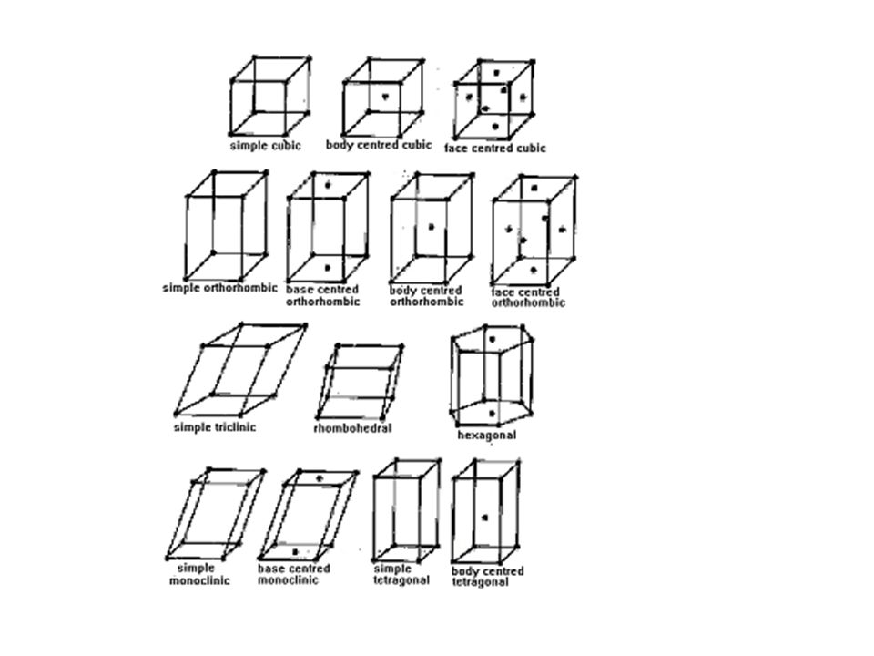
Bravais Lattices Bravais lattices describe the geometric arrangement of the individual lattice points within each of the seven crystal systems. There are fourteen Bravais lattices which are distinct from one another in the translational symmetry they contain, and all crystalline minerals fit in one of these unique fourteen arrangements. Unit Cell The "unit cell" is the smallest divisible unit of a given mineral with symmetrical characteristics that are unique to its crystalline structure. A structure's unit-cell is a spatial arrangement of atoms (motifs) which are "tiled" in a three-dimensional space to form the crystal. The unit-cell's form is determined by its unique "lattice" parameters, the length of the cell edges, and the angles between them. The positions of the atoms inside the unit-cell are described by the set of atomic positions (xi,yi,zi) measured from a given lattice point.
 which are tiled in a three-dimensional space to form the crystal. The unit-cell s form is determined by its unique lattice parameters, the length of the cell edges, and the angles between them. The positions of the atoms inside the unit-cell are described by the set of atomic positions (xi,yi,zi) measured from a given lattice point.")
44
Unit Cells

47
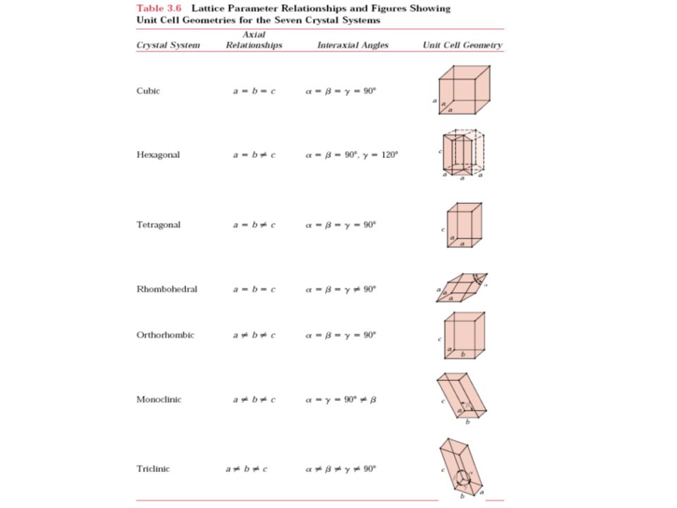
Each crystal system consists of a set of three axes in a particular geometrical arrangement. The seven unique crystal systems, listed in order of decreasing symmetry, are: 1. Isometric System, 2. Hexagonal System, 3. Tetragonal System, 4. Rhombohedric (Trigonal) System, 5. Orthorhombic System, 6. Monoclinic System, 7. Triclinic System.
 System, 5. Orthorhombic System, 6. Monoclinic System, 7. Triclinic System..")
50
The Seven Crystal Systems
1. Cubic The cubic crystal system is also known as the "isometric" system. The cubic (Isometric) crystal system is characterized by its total symmetry. The Cubic system has three crystallographic axes that are all perpendicular to each other, and equal in length. The cubic system has one lattice point on each of the cube's four corners.
 crystal system is characterized by its total symmetry. The Cubic system has three crystallographic axes that are all perpendicular to each other, and equal in length. The cubic system has one lattice point on each of the cube s four corners.")
51
2. Hexagonal The hexagonal crystal system has four crystallographic axes consisting of three equal horizontal or equatorial (a, b, and d) axes at 120º, and one vertical (c) axis that is perpendicular to the other three. The (c) axis can be shorter, or longer than the horizontal axes.
 axes at 120º, and one vertical (c) axis that is perpendicular to the other three. The (c) axis can be shorter, or longer than the horizontal axes.")
52
3. Tetragonal A tetragonal crystal is a simple cubic shape that is stretched along its (c) axis to form a rectangular prism. The tetragonal crystal will have a square base and top, but a height which is taller. By continuing to stretch the "body-centered" cubic, one more Bravais lattice of the tetragonal system is constructed.
 axis to form a rectangular prism. The tetragonal crystal will have a square base and top, but a height which is taller. By continuing to stretch the body-centered cubic, one more Bravais lattice of the tetragonal system is constructed.")
53
4. Rhombohedral A rhombohedron (aka trigonal system) has a three-dimensional shape that is similar to a cube, but it has been skewed or inclined to one side making it oblique. Its form is considered "prismatic" because all six crystal faces are parallel to each other. Any faces that are not squared at right angels are called "rhombi." A rhombohedral crystal has six faces, 12 edges, and 8 vertices. If all of the non-obtuse internal angles of the faces are equal (flat sample, below), it can be called a trigonal-trapezohedron.
 has a three-dimensional shape that is similar to a cube, but it has been skewed or inclined to one side making it oblique. Its form is considered prismatic because all six crystal faces are parallel to each other. Any faces that are not squared at right angels are called rhombi. A rhombohedral crystal has six faces, 12 edges, and 8 vertices. If all of the non-obtuse internal angles of the faces are equal (flat sample, below), it can be called a trigonal-trapezohedron.")
54
5. Orthorhombic Minerals that form in the orthorhombic (aka rhombic) crystal system have three mutually perpendicular axes, all with different, or unequal lengths.
 crystal system have three mutually perpendicular axes, all with different, or unequal lengths.")
55
6. Monoclinic Crystals that form in the monoclinic system have three unequal axes. The (a) and (c) crystallographic axes are inclined toward each other at an oblique angle, and the (b) axis is perpendicular to a and c. The (b) crystallographic axis is called the "ortho" axis.
 and (c) crystallographic axes are inclined toward each other at an oblique angle, and the (b) axis is perpendicular to a and c. The (b) crystallographic axis is called the ortho axis.")
56
7. Triclinic Crystals that form in the triclinic system have three unequal crystallographic axes, all of which intersect at oblique angles. Triclinic crystals have a 1-fold symmetry axis with virtually no discernible symmetry, and no mirrored or prismatic planes.

57
Cristalografia

58
Origem do sistema de coordenadas
O espaço lático é infinito... A escolha de uma origem é completamente arbitrária, uma vez que cada ponto do reticulado cristalino idêntico. A designação de pontos, direções e planos específicos fixados no espaço absoluto serão alterados caso a origem seja mudada, MAS ... todas as designações serão auto-consistentes se partirem da origem como uma referência absoluta. Exemplo: Dada uma origem qualquer, haverá sempre uma direção [110] definida univocamente, e [110] sempre fará exatamente o mesmo ângulo com a direção [100].

59
DIREÇÕES NOS CRISTAIS São representadas entre colchetes=[uvw]
Família de direções: <uvw>
![DIREÇÕES NOS CRISTAIS São representadas entre colchetes=[uvw]](http://slideplayer.com.br/slide/1249788/3/images/59/DIRE%C3%87%C3%95ES+NOS+CRISTAIS+S%C3%A3o+representadas+entre+colchetes%3D%5Buvw%5D.jpg "Família de direções: <uvw>")
60
DIREÇÕES? (o,o,o)
")
61
Algumas direções da família de direções <100>

62
DIREÇÕES NOS CRISTAIS São representadas entre colchetes= [hkl]
Se a subtração der negativa, coloca-se uma barra sobre o número
![DIREÇÕES NOS CRISTAIS São representadas entre colchetes= [hkl]](http://slideplayer.com.br/slide/1249788/3/images/62/DIRE%C3%87%C3%95ES+NOS+CRISTAIS+S%C3%A3o+representadas+entre+colchetes%3D+%5Bhkl%5D.jpg "Se a subtração der negativa, coloca-se uma barra sobre o número.")
63
As duas direções pertencem a mesma família? [101]
![As duas direções pertencem a mesma família [101]](http://slideplayer.com.br/slide/1249788/3/images/63/As+duas+dire%C3%A7%C3%B5es+pertencem+a+mesma+fam%C3%ADlia+%5B101%5D.jpg "As duas direções pertencem a mesma família [101]")
64
DIREÇÕES NOS CRISTAIS São representadas entre colchetes= [hkl]
Quando passa pela origem
![DIREÇÕES NOS CRISTAIS São representadas entre colchetes= [hkl]](http://slideplayer.com.br/slide/1249788/3/images/64/DIRE%C3%87%C3%95ES+NOS+CRISTAIS+S%C3%A3o+representadas+entre+colchetes%3D+%5Bhkl%5D.jpg "Quando passa pela origem.")
65
DIREÇÕES NOS CRISTAIS São representadas entre colchetes= [hkl]
Os números devem ser divididos ou multiplicados por um fator comum para dar números inteiros
![DIREÇÕES NOS CRISTAIS São representadas entre colchetes= [hkl]](http://slideplayer.com.br/slide/1249788/3/images/65/DIRE%C3%87%C3%95ES+NOS+CRISTAIS+S%C3%A3o+representadas+entre+colchetes%3D+%5Bhkl%5D.jpg "Os números devem ser divididos. ou multiplicados por um. fator comum para dar números. inteiros.")
66
DIREÇÕES PARA O SISTEMA CÚBICO
A simetria desta estrutura permite que as direções equivalentes sejam agrupadas para formar uma família de direções: <100> para as faces <110> para as diagonais das faces <111> para a diagonal do cubo <110> <111> <100>

67
DIREÇÕES PARA O SISTEMA CCC
No sistema ccc os átomos se tocam ao longo da diagonal do cubo, que corresponde a família de direções <111> Então, a direção <111> é a de maior empacotamento atômico para o sistema ccc

68
DIREÇÕES PARA O SISTEMA CFC
No sistema cfc os átomos se tocam ao longo da diagonal da face, que corresponde a família de direções <110> Então, a direção <110> é a de maior empacotamento atômico para o sistema cfc Filme 22

69
PLANOS CRISTALINOS Por quê são importantes?
· Para a determinação da estrutura cristalina Os métodos de difração medem diretamente a distância entre planos paralelos de pontos do reticulado cristalino. Esta informação é usada para determinar os parâmetros do reticulado de um cristal. Os métodos de difração também medem os ângulos entre os planos do reticulado. Estes são usados para determinar os ângulos interaxiais de um cristal. · Para a deformação plástica A deformação plástica (permanente) dos metais ocorre pelo deslizamento dos átomos, escorregando uns sobre os outros no cristal. Este deslizamento tende a acontecer preferencialmente ao longo de planos direções específicos do cristal. · Para as propriedades de transporte Em certos materiais, a estrutura atômica em determinados planos causa o transporte de elétrons e/ou acelera a condução nestes planos, e, relativamente, reduz a velocidade em planos distantes destes. Exemplo 1: Grafita A condução de calor é mais rápida nos planos unidos covalentemente sp2 do que nas direções perpendiculares a esses planos. Exemplo 2: supercondutores a base de YBa2Cu3O7 Alguns planos contêm somente Cu e O. Estes planos conduzem pares de elétrons (chamados pares de cobre) que são os responsáveis pela supercondutividade. Estes supercondutores são eletricamente isolantes em direções perpendiculares as dos planos Cu-O.
 dos metais ocorre pelo deslizamento dos átomos, escorregando uns sobre os outros no cristal. Este deslizamento tende a acontecer preferencialmente ao longo de planos direções específicos do cristal. · Para as propriedades de transporte. Em certos materiais, a estrutura atômica em determinados planos causa o transporte de elétrons e/ou acelera a condução nestes planos, e, relativamente, reduz a velocidade em planos distantes destes. Exemplo 1: Grafita. A condução de calor é mais rápida nos planos unidos covalentemente sp2 do que nas direções perpendiculares a esses planos. Exemplo 2: supercondutores a base de YBa2Cu3O7. Alguns planos contêm somente Cu e O. Estes planos conduzem pares de elétrons (chamados pares de cobre) que são os responsáveis pela supercondutividade. Estes supercondutores são eletricamente isolantes em direções perpendiculares as dos planos Cu-O.")
70
PLANOS CRISTALINOS São representados de maneira similar às direções
São representados pelos índices de Miller = (hkl) Planos paralelos são equivalentes tendos os mesmos índices
 Planos paralelos são equivalentes tendos os mesmos índices.")
71
PLANOS CRISTALINOS

72
PLANOS CRISTALINOS Planos (010)
São paralelos aos eixos x e z (paralelo à face) Cortam um eixo (neste exemplo: y em 1 e os eixos x e z em ) 1/ , 1/1, 1/ = (010)
 Cortam um eixo (neste exemplo: y em 1 e os eixos x e z em ) 1/ , 1/1, 1/ = (010)")
73
PLANOS CRISTALINOS Planos (110) São paralelos a um eixo (z)
Cortam dois eixos (x e y) 1/ 1, 1/1, 1/ = (110)
 1/ 1, 1/1, 1/ = (110)")
74
PLANOS CRISTALINOS Planos (111) Cortam os 3 eixos cristalográficos
1/ 1, 1/1, 1/ 1 = (111)
")
75
PLANOS CRISTALINOS Quando as intercessões não são óbvias desloca-se o plano até obter as intercessões corretas Fonte: Prof. Sidnei Paciornik, Departamento de Ciência dos Materiais e Metalurgia da PUC-Rio

76
FAMÍLIA DE PLANOS {110} É paralelo à um eixo

77
FAMÍLIA DE PLANOS {111} Intercepta os 3 eixos

78
PLANOS NO SISTEMA CÚBICO
A simetria do sistema cúbico faz com que a família de planos tenham o mesmo arranjamento e densidade Deformação em metais envolve deslizamento de planos atômicos. O deslizamento ocorre mais facilmente nos planos e direções de maior densidade atômica

79
PLANOS DE MAIOR DENSIDADE ATÔMICA NO SISTEMA CCC
A família de planos {110} no sistema ccc é o de maior densidade atômica

80
PLANOS DE MAIOR DENSIDADE ATÔMICA NO SISTEMA CFC
A família de planos {111} no sistema cfc é o de maior densidade atômica

81
DENSIDADE ATÔMICA LINEAR E PLANAR
Densidade linear= átomos/cm (igual ao fator de empacotamento em uma dimensão) Densidade planar= átomos/unidade de área (igual ao fator de empacotamento em duas dimensões)
 Densidade planar= átomos/unidade de área (igual ao fator de empacotamento em duas dimensões)")
82
DETERMINAÇÃO DA ESTRUTURA CRISTALINA POR DIFRAÇÃO DE RAIO X
Raíos-x tem comprimento de onda similar a distância interplanar 0,1nm

83
DETERMINAÇÃO DA ESTRUTURA CRISTALINA POR DIFRAÇÃO DE RAIO X
O FENÔMENO DA DIFRAÇÃO: Quando um feixe de raios x é dirigido à um material cristalino, esses raios são difratados pelos planos dos átomos ou íons dentro do cristal

84
DETERMINAÇÃO DA ESTRUTURA CRISTALINA POR DIFRAÇÃO DE RAIO X
Fonte: Prof. Sidnei Paciornik, Departamento de Ciência dos Materiais e Metalurgia da PUC-Rio

85
DIFRAÇÃO DE RAIOS X LEI DE BRAGG
n= 2 dhkl.sen É comprimento de onda N é um número inteiro de ondas d é a distância interplanar O ângulo de incidência Válido para sistema cúbico dhkl= a (h2+k2+l2)1/2
1/2.")
86
DISTÂNCIA INTERPLANAR (dhkl)
É uma função dos índices de Miller e do parâmetro de rede dhkl= a (h2+k2+l2)1/2
1/2.")
87
TÉCNICAS DE DIFRAÇÃO Técnica do pó:
É bastante comum, o material a ser analisado encontra-se na forma de pó (partículas finas orientadas ao acaso) que são expostas à radiação x monocromática. O grande número de partículas com orientação diferente assegura que a lei de Bragg seja satisfeita para alguns planos cristalográficos
 que são expostas à radiação x monocromática. O grande número de partículas com orientação diferente assegura que a lei de Bragg seja satisfeita para alguns planos cristalográficos.")
88
O DIFRATOMÊTRO DE RAIOS X
T= fonte de raio X S= amostra C= detector O= eixo no qual a amostra e o detector giram Amostra Fonte Detector

89
DIFRATOGRAMA Fonte: Prof. Sidnei Paciornik, Departamento de
Ciência dos Materiais e Metalurgia da PUC-Rio

90
Mais sobre o Silício

91
Diamond Cubic The diamond cubic structure consists of two interpenetrating face-centered cubic lattices, with one offset 1/4 of a cube along the cube diagonal. It may also be described as face centered cubic lattice in which half of the tetrahedral sites are filled while all the octahedral sites remain vacant. The diamond cubic unit cell is shown in Figure 8. Each of the atoms (e.g., C) is four coordinate, and the shortest interatomic distance (C-C) may be determined from the unit cell parameter (a). Eq1.jpg(1) Figure 8: Unit cell structure of a diamond cubic lattice showing the two interpenetrating face-centered cubic lattices.Figure 8 (graphics16.png)
 is four coordinate, and the shortest interatomic distance (C-C) may be determined from the unit cell parameter (a). Eq1.jpg(1) Figure 8: Unit cell structure of a diamond cubic lattice showing the two interpenetrating face-centered cubic lattices.Figure 8 (graphics16.png)")
Apresentações semelhantes