Carregar apresentação
A apresentação está carregando. Por favor, espere

1
Índice de refração negativo
2
Índice de refração: Valor positivo – Valor negativo?
Positivo Conforme nos ensinaram (regra da mão direita) Negativo Nos dias de hoje (regra da mão esquerda)
 Negativo Nos dias de hoje (regra da mão esquerda)")
3
Lembrando conforme nos ensinaram
Lei de refração Para n1 = 1

4
Outras relações Lei de Snell

5
Índice de refração negativo
Termos usados Meio Veselago Material duplamente negativo Metamaterial (Meta = Além) Meio de mão esquerda Meio reverso
 Meio de mão esquerda. Meio reverso.")
6
O que é? Em geral todo material possui dois parâmetros físicos que o caracterizam: - permitividade e - permeabilidade m Esses dois parâmetros determinam como o material irá interagir com a radiação eletromagnética. Normalmente ambos são positivos, no entanto no caso de índice de refração negativo, ambos são negativos (por isso material duplamente negativo).
.")
7
Amfoterismo? - Amfotérico?
Feito de/ou que possui dois componentes Óxidos amfotéricos de Zn, Sn, Al, Be entre outros. E.g. O ZnO reage conforme o pH da solução: ZnO + 2H+ --> Zn2+ + H2O em solução ácida ZnO + H2O + 2OH- --> [Zn(OH)4] em solução básica
4]2- em solução básica.")
8
nmaterial = 1 nmaterial > 1 1 > nmaterial > 0
Refração do ar para o material 1 > nmaterial > 0 nmaterial < 0

9
Metamaterial A negative−index material will refract light through a negative angle. (a) In this simulation17 of a Snell's law experiment, a negative−index wedge with ε = −1 and μ = −1 deflects an electromagnetic beam by a negative angle relative to the surface normal: The beam emerges on the same side of the surface normal as the incident beam. Color represents intensity: red, highest; blue, lowest. (b) A positive−index wedge, in contrast, will positively refract the same beam. Red lines trace the path of the beams, and the surface normals are shown in black. Experiments confirm this behavior. (c) The deflection angle (horizontal axis) observed for a beam traversing a negative wedge as a function of frequency (vertical axis). (d) The deflection angle observed for a positive−index Teflon® wedge as a function of frequency. In the negative wedge there is strong dispersion with frequency: The condition ε = −1, μ = −1 is realized only over a narrow bandwidth around 12 GHz.
 In this simulation17 of a Snell s law experiment, a negative−index wedge with ε = −1 and μ = −1 deflects an electromagnetic beam by a negative angle relative to the surface normal: The beam emerges on the same side of the surface normal as the incident beam. Color represents intensity: red, highest; blue, lowest. (b) A positive−index wedge, in contrast, will positively refract the same beam. Red lines trace the path of the beams, and the surface normals are shown in black. Experiments confirm this behavior. (c) The deflection angle (horizontal axis) observed for a beam traversing a negative wedge as a function of frequency (vertical axis). (d) The deflection angle observed for a positive−index Teflon® wedge as a function of frequency. In the negative wedge there is strong dispersion with frequency: The condition ε = −1, μ = −1 is realized only over a narrow bandwidth around 12 GHz.")
10
http://physicsworld.com/cws/article/print/17398 Physics in Action
May 1, 2003 Negative-index materials are now a reality, as a recent experiment at MIT has shown. (a) Light travelling upwards is refracted in the positive direction (right) when it leaves a Teflon wedge. (b) A metamaterial consisting of wires and rings causes light to be refracted in the opposite direction (left) when it exits, thereby demonstrating that it has a negative index of refraction.
 Light travelling upwards is refracted in the positive direction (right) when it leaves a Teflon wedge. (b) A metamaterial consisting of wires and rings causes light to be refracted in the opposite direction (left) when it exits, thereby demonstrating that it has a negative index of refraction.")
11
Propagação no meio Mão esquerda Mão direita Outros modelos:
A) Pendrys_P_L_xy.wmv B) Pendrys_Perfect_Lens_3D.wmv
 Pendrys_P_L_xy.wmv. B) Pendrys_Perfect_Lens_3D.wmv.")
12
Metamaterial para microondas

13
Outros sistemas ressonantes na geração de metamateriais para microondas

14
Principio de Fermat Principio de Fermat: “A trajetória da luz, ao passar de um ponto para outro, é tal que o tempo do percurso é estacionário em relação a variações na trajetória.” Como abordar o principio de Fermat para o caso de índice de refração negativo?

16
Forma não-convencional, n<0
Aplicação Forma clássica, n>0 Forma não-convencional, n<0

17
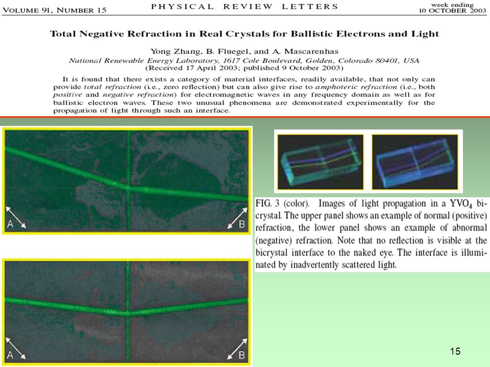
Refração negativa - imagem

18
Aplicações Normal n1 n2 Metamaterial n1 n2

19
Lentes? Limites de observação com luz visível Superlentes Hiperlentes

20
Superlente - Hiperlente
Conventional, positive-refractive-index lenses create images by capturing the light waves emitted by an object and then bending them. However, objects also emit "evanescent" waves that contain a lot of information at very small scales about the object. These waves are much harder to measure because they decay exponentially and never reach the image plane - a threshold in optics known as the diffraction limit. A drawing of nano-scale imaging using a silver superlens that achieves a resolution beyond the optical diffraction limit. The red line indicates the enhancement of "evanescent" waves as they pass through the superlens. (Image: Cheng Sun, UC Berkeley) HIPERLENTE: Schematic of an optical hyperlens that can magnify and project sub-diffraction-limited objects onto a far-field plane. The objects and the hyperlens are enlarged to show details; they are actually much smaller than a conventional lens. Images courtesy the Zhang Lab, UC Berkeley Scientists at the University of California, Berkeley, have developed a "hyperlens" that brings them one major step closer to the goal of nanoscale optical imaging. The new hyperlens, described in the Feb. 23 issue of the journal Science, is capable of projecting a magnified image of a pair of nanowires spaced 150 nanometers apart onto a plane up to a meter away. Currently, to capture details down to a few nanometers, scientists must use scanning electron or atomic force microscopes, which create images by scanning objects point by point. Scanning electron microscopes can take up to several minutes to get an image. Because the object must remain immobile and in a vacuum during this process, imaging is restricted to non-living samples.
 HIPERLENTE: Schematic of an optical hyperlens that can magnify and project sub-diffraction-limited objects onto a far-field plane. The objects and the hyperlens are enlarged to show details; they are actually much smaller than a conventional lens. Images courtesy the Zhang Lab, UC Berkeley. Scientists at the University of California, Berkeley, have developed a hyperlens that brings them one major step closer to the goal of nanoscale optical imaging. The new hyperlens, described in the Feb. 23 issue of the journal Science, is capable of projecting a magnified image of a pair of nanowires spaced 150 nanometers apart onto a plane up to a meter away. Currently, to capture details down to a few nanometers, scientists must use scanning electron or atomic force microscopes, which create images by scanning objects point by point. Scanning electron microscopes can take up to several minutes to get an image. Because the object must remain immobile and in a vacuum during this process, imaging is restricted to non-living samples.")
21
Próximo tema conectores

Apresentações semelhantes


 Princípio de menos tempo (Fermat)>")


