Carregar apresentação
A apresentação está carregando. Por favor, espere

1
Resumo da aula passada Apresentação do Armando sobre "Como Funciona? 10 dispositivos que você sempre quis saber como funciona“ Termoluminescência TL e Luminescência Opticamente Estimulada OSL Defeitos em vidros, materiais fotorefrativos, fotoexpansão, fotocontração. Formação de rede e microlentes com espelho de Lloyd. Interferômetro de Fabry-Perot como aplicação para rede de Bragg e filtros em fibras e sistemas planares. Descoberta da rede de Bragg em fibras. Produção de redes de Bragg. dispoptic 2013

2
Aula de Hoje Aplicações com Rede de Bragg. Diversas configurações.
Moduladores ópticos Litografia Aula prática? Óptica integrada dispoptic 2013

3
Redes de Bragg em sensores
Development of Bragg Grating Sensor-Cefet.pdf Demonstration of etched cladding fiber Bragg grating-based sensor with hydrogel coating.pdf Discrimination methods and demodulation techniques for fiber.pdf Fiber Bragg Grating Technology pdf Reliability of Fiber Bragg Grating Based Sensors for Downhole Applications.pdf Gratings written into fibers provide a mechanism for sensing strain dispoptic 2013

4
Montagem de sistema para sensor FBG
dispoptic 2013

5
Aplicação monitoramento de temperatura. Sinal de FBG e de termopar
dispoptic 2013

6
dispoptic 2013

7
Resumo de aplicações de FBG’s
Deformação axial Deformação transversal Deformação cisalhamento Temperatura Umidade Acústica Vibração Composição química dispoptic 2013

8
Um pouco mais The Gratings Reflect In this example, the red wavelength matches the grating period and is reflected. The blue wavelength is transmitted because it does not match the grating spacings. (Illustration assistance courtesy of Jeff Hecht.) Optical Circulators Since the desired wavelength is reflected back by the grating, another device known as an "optical circulator" detects and switches it. (Illustration courtesy of Jeff Hecht.) dispoptic 2013
 Optical Circulators Since the desired wavelength is reflected back by the grating, another device known as an optical circulator detects and switches it. (Illustration courtesy of Jeff Hecht.) dispoptic")
9
Tutoriais => surface relief (SR) fbg => fbg dispoptic 2013

10
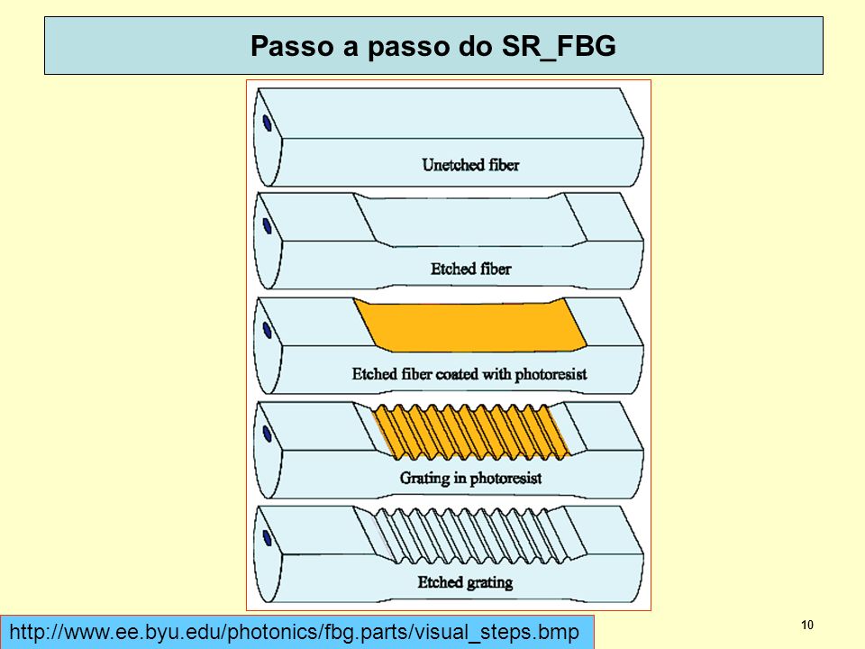
Passo a passo do SR_FBG dispoptic 2013
11
Calculadora de rede de Bragg
figure: When a Bragg grating exists in an optical fiber, it will reflect a specific wavelength dependent on the period of the Bragg grating and the index of refraction of the optical fiber. This calculator finds the period of Bragg grating needed for a predetermined wavelength and index of refraction. dispoptic 2013

12
Calculadora da periodicidade numa FBG
dispoptic 2013

13
Um compacto sobre redes de Bragg IPHT – Jena (Institute of Photonic Technology)
FiberBragg_Ecke_tutorial.pdf dispoptic 2013

14
Ainda mais um pouco sobre rede Bragg
Tipos de redes em fibras. (a) Rede de Bragg em fibra, (b) Rede de período longo, (c) Rede trinada- mistura de período longo com curto, (d) Rede inclinada ou deitada, (e) Rede de teste. Fig. 3. Types of fiber gratings. (a) Fiber Bragg grating, (b) long-period fiber grating, (c) chirped fiber grating, (d) tilted fiber grating, (e) sampled fiber grating. 2. Fiber grating sensors Although the formation of fiber gratings had been reported in 1978 [7], intensive study on fiber gratings began after a controllable and effective method for their fabrication was devised in 1989 [8]. Fiber gratings have been applied to add/drop filters, amplifier gain flattening filters, dispersion compensators, fiber lasers and so on for optical communications [4]. Extensive studies have also been performed on fiber grating sensors and some of which have now reached commercialization stages. Figure 3 shows types of fiber gratings. Under phase matching conditions, a fiber Bragg grating (FBG) couples the forward propagating core mode to the backward propagating core mode. A long-period fiber grating (LPG) can couple the forward propagating core mode to one or a few of the forward propagating cladding modes. A chirped fiber grating has a wider reflection spectrum and each wavelength component is reflected at different positions, which results in a delay time difference for different reflected wavelengths. A tilted fiber grating can couple the forward propagating core mode to the backward propagating core mode and a backward propagating cladding mode. A sampled fiber grating can reflect several wavelength components with equal wavelength spacing. All these types of gratings have been utilized in various types of fiber grating sensors and wavelength change interrogators. Among them, however, FBGs are the most widely used as sensor heads. In FBGs the Bragg wavelength λB, or the wavelength of the light that is reflected, is given by λB = 2neffΛ, Chirp = chilrear, chilrar chilrear, chilrar (cat. verbal)domínios: Seres Vivos glosa: emitir som prolongado e modulado, característico de certos pássaros de pequeno porte exemplo: É muito agradável ouvir o rouxinol chilrear/chilrar. Tilted = inclinado Effective Refractive Index In homogeneous transparent media, the refractive index n can be used to quantify the increase in the wavenumber (phase change per unit length) caused by the medium: the wavenumber is n times higher than it would be in vacuum. The effective refractive index neff has the analogous meaning for light propagation in a waveguide; the propagation constant is the effective index times the vacuum wavenumber: Note that the effective refractive index depends not only on the wavelength but also (for multimode waveguides) on the mode in which the light propagates. For this reason, it is also called modal index. The effective index may be a complex quantity. In that case, the imaginary part describes gain or loss – see the article on propagation constant for mode details. A common but wrong belief is that the effective refractive index is a kind of weighted average of the refractive index of core and cladding of the waveguide, with the weight factors determined by the fractions of the optical power propagating in the core and cladding. This impression may result from the common observation that higher-order modes, e.g. of a fiber, have a lower effective index and also a lower mode overlap with the core. However, consider e.g. a step-index multimode waveguide with a high numerical aperture and large core diameter. Here, all modes overlap to nearly 100% with the core (i.e. the mode overlaps are very similar), whereas the effective indices differ substantially. Effective Refractive Index: Correcting a Common Belief While the refractive index of a homogeneous transparent medium is based on a rather simple concept, the effective refractive index in a waveguide such as e.g. an optical fiber is somewhat more difficult to understand – and is in fact often misunderstood. In a usual single-mode fiber, the guided propagation mode extends significantly beyond the region of the fiber core, and the effective refractive index is found to have a value somewhat between the refractive indices of core and cladding. In a multimode fiber, higher-order modes extend more into the cladding, and have smaller effective indices. These facts often make people believe that the effective index is a kind of weighted average of the local refractive index, according to the propagation of some parts of the total optical power in the core and in the cladding, respectively. This picture, however, is quite wrong. First consider the definition of the effective index neff: the propagation constant of some fiber mode is neff times the vacuum wavenumber. So that definition targets the phase change per unit length along the fiber axis, not the intensity distribution. Still one might guess that there is some relation to the intensity distribution as well, but a simple example shows that this can hardly be true. Consider a step-index multimode fiber with high numerical aperture (NA), i.e., with a very large index step. In that case, all fiber modes propagate essentially only in the core, so that from this one might expect the effective index of all modes to closely match the core index. But this is not the case: higher-order modes still have significantly lower effective indices. They experience a smaller phase shift per unit length, even though they propagate in the same material. How can that be? Essentially it is the fact that higher-order modes contain more pronounced plane wave components (spatial Fourier components) with a larger angular offset from the fiber axis. So it is here in some sense a matter of different propagation directions, not of different materials. Of course, both effects are relevant in fibers with lower NA. One detail can still be confusing: shouldn't modes with stronger off-axis field components experience a larger rather than a smaller phase shift per unit length, given that they somehow have to travel a larger distance? No, that is actually not true: when the k vector has some angle to the fiber axis, its projection to the fiber axis becomes smaller, reducing the phase changes in that direction. This is somewhat reminiscent of a phenomenon discussed in an earlier spotlight article, where that aspect has been discussed in some detail. λB = 2neffΛ dispoptic 2013
 Rede de Bragg em fibra, (b) Rede de período longo, (c) Rede trinada- mistura de período longo com curto, (d) Rede inclinada ou deitada, (e) Rede de teste. Fig. 3. Types of fiber gratings. (a) Fiber Bragg grating, (b) long-period fiber grating, (c) chirped fiber grating, (d) tilted fiber grating, (e) sampled fiber grating. 2. Fiber grating sensors. Although the formation of fiber gratings had been reported in 1978 [7], intensive study on fiber gratings began after a controllable and effective method for their fabrication was devised in 1989 [8]. Fiber gratings have been applied to add/drop filters, amplifier gain flattening filters, dispersion compensators, fiber lasers and so on for optical communications [4]. Extensive studies have also been performed on fiber grating sensors and some of which have now reached commercialization stages. Figure 3 shows types of fiber gratings. Under phase matching conditions, a fiber Bragg grating (FBG) couples the forward propagating core mode to the backward propagating core mode. A long-period fiber grating (LPG) can couple the forward propagating core mode to one or a few of the forward propagating cladding modes. A chirped fiber grating has a wider reflection spectrum and each wavelength component is reflected at different positions, which results in a delay time difference for different reflected wavelengths. A tilted fiber grating can couple the forward propagating core mode to the backward propagating core mode and a backward propagating cladding mode. A sampled fiber grating can reflect several wavelength components with equal wavelength spacing. All these types of gratings have been utilized in various types of fiber grating sensors and wavelength change interrogators. Among them, however, FBGs are the most widely used as sensor heads. In FBGs the Bragg wavelength λB, or the wavelength of the light that is reflected, is given by. λB = 2neffΛ, Chirp = chilrear, chilrar. chilrear, chilrar (cat. verbal)domínios: Seres Vivos glosa: emitir som prolongado e modulado, característico de certos pássaros de pequeno porte exemplo: É muito agradável ouvir o rouxinol chilrear/chilrar. Tilted = inclinado. Effective Refractive Index. In homogeneous transparent media, the refractive index n can be used to quantify the increase in the wavenumber (phase change per unit length) caused by the medium: the wavenumber is n times higher than it would be in vacuum. The effective refractive index neff has the analogous meaning for light propagation in a waveguide; the propagation constant is the effective index times the vacuum wavenumber: Note that the effective refractive index depends not only on the wavelength but also (for multimode waveguides) on the mode in which the light propagates. For this reason, it is also called modal index. The effective index may be a complex quantity. In that case, the imaginary part describes gain or loss – see the article on propagation constant for mode details. A common but wrong belief is that the effective refractive index is a kind of weighted average of the refractive index of core and cladding of the waveguide, with the weight factors determined by the fractions of the optical power propagating in the core and cladding. This impression may result from the common observation that higher-order modes, e.g. of a fiber, have a lower effective index and also a lower mode overlap with the core. However, consider e.g. a step-index multimode waveguide with a high numerical aperture and large core diameter. Here, all modes overlap to nearly 100% with the core (i.e. the mode overlaps are very similar), whereas the effective indices differ substantially Effective Refractive Index: Correcting a Common Belief. While the refractive index of a homogeneous transparent medium is based on a rather simple concept, the effective refractive index in a waveguide such as e.g. an optical fiber is somewhat more difficult to understand – and is in fact often misunderstood. In a usual single-mode fiber, the guided propagation mode extends significantly beyond the region of the fiber core, and the effective refractive index is found to have a value somewhat between the refractive indices of core and cladding. In a multimode fiber, higher-order modes extend more into the cladding, and have smaller effective indices. These facts often make people believe that the effective index is a kind of weighted average of the local refractive index, according to the propagation of some parts of the total optical power in the core and in the cladding, respectively. This picture, however, is quite wrong. First consider the definition of the effective index neff: the propagation constant of some fiber mode is neff times the vacuum wavenumber. So that definition targets the phase change per unit length along the fiber axis, not the intensity distribution. Still one might guess that there is some relation to the intensity distribution as well, but a simple example shows that this can hardly be true. Consider a step-index multimode fiber with high numerical aperture (NA), i.e., with a very large index step. In that case, all fiber modes propagate essentially only in the core, so that from this one might expect the effective index of all modes to closely match the core index. But this is not the case: higher-order modes still have significantly lower effective indices. They experience a smaller phase shift per unit length, even though they propagate in the same material. How can that be Essentially it is the fact that higher-order modes contain more pronounced plane wave components (spatial Fourier components) with a larger angular offset from the fiber axis. So it is here in some sense a matter of different propagation directions, not of different materials. Of course, both effects are relevant in fibers with lower NA. One detail can still be confusing: shouldn t modes with stronger off-axis field components experience a larger rather than a smaller phase shift per unit length, given that they somehow have to travel a larger distance No, that is actually not true: when the k vector has some angle to the fiber axis, its projection to the fiber axis becomes smaller, reducing the phase changes in that direction. This is somewhat reminiscent of a phenomenon discussed in an earlier spotlight article, where that aspect has been discussed in some detail. λB = 2neffΛ. dispoptic")
15
Antes de entrar com Óptica Integrada
Moduladores ópticos Litografia aula prática? óptica integrada dispoptic 2013

16
Modulação Modular = informação + portador eletrônico ou óptico
Sinais em comunicações normalmente possuem duas componentes: O sinal próprio da informação O sinal da portadora Como modular, o quê modular? Portador: Exemplo básico de modulação: The point to modulation is to take a message bearing signal and superimpose it upon a carrier signal for transmission. For ease of transmission carrier signals are generally high frequency for severable reasons: 1.- For easy (low loss, low dispersion) propagation as electromagnetic waves 2.- So that they may be simultaneously transmitted without interference from other signals 3.- So as to enable the construction of small antennas (a fraction, usually a quarter of the wavelength) 4.- So as to be able to multiplex that is to combine multiple signals for transmission at the same time. For example AM radio is KHz, FM radio is 88 MHz-108 MHz, TV is MHz (channels 1-6), MHz (channels 7-12) and MHz (UHF), microwave and satellite signals are of the order of several GHz and infra red fiber optic signals are of the order of THz. modulation - Modulation is the addition of information (or the signal) to an electronic or optical signal carrier. Modulation can be applied to direct current (mainly by turning it on and off), to alternating current, and to optical signals. One can think of blanket waving as a form of modulation used in smoke signal transmission (the carrier being a steady stream of smoke). Morse code, invented for telegraphy and still used in amateur radio, uses a binary (two-state) digital code similar to the code used by modern computers. For most of radio and telecommunication today, the carrier is alternating current (AC) in a given range of frequencies. Common modulation methods include: Amplitude modulation (AM), in which the voltage applied to the carrier is varied over time Frequency modulation (FM), in which the frequency of the carrier waveform is varied in small but meaningful amounts Phase modulation (PM), in which the natural flow of the alternating current waveform is delayed temporarily These are sometimes known as continuous wave modulation methods to distinguish them from pulse code modulation (PCM), which is used to encode both digital and analog information in a binary way. Radio and television broadcast stations typically use AM or FM. Most two-way radios use FM, although some employ a mode known as single sideband (SSB). More complex forms of modulation are Phase Shift Keying (PSK) and Quadrature Amplitude Modulation (QAM). Optical signals are modulated by applying an electromagnetic current to vary the intensity of a laser beam. Modem Modulation and Demodulation A computer with an online or Internet connection that connects over a regular analog phone line includes a modem. This term is derived by combining beginning letters from the words modulator and demodulator. In a modem, the modulation process involves the conversion of the digital computer signals (high and low, or logic 1 and 0 states) to analog audio-frequency (AF) tones. Digital highs are converted to a tone having a certain constant pitch; digital lows are converted to a tone having a different constant pitch. These states alternate so rapidly that, if you listen to the output of a computer modem, it sounds like a hiss or roar. The demodulation process converts the audio tones back into digital signals that a computer can understand. directly. Multiplexing More information can be conveyed in a given amount of time by dividing the bandwidth of a signal carrier so that more than one modulated signal is sent on the same carrier. Known as multiplexing, the carrier is sometimes referred to as a channel and each separate signal carried on it is called a subchannel. (In some usages, each subchannel is known as a channel.) The device that puts the separate signals on the carrier and takes them off of received transmissions is a multiplexer. Common types of multiplexing include frequency-division multiplexing (FDM) and time-division multiplexing (TDM). FDM is usually used for analog communication and divides the main frequency of the carrier into separate subchannels, each with its own frequency band within the overall bandwidth. TDM is used for digital communication and divides the main signal into time-slots, with each time-slot carrying a separate signal. CONTRIBUTORS:Wai Yin LamLAST UPDATED:10 Jul 2005 Passar uma “cola” Embrulhar a “cola” num lápis e jogar A “cola”é a informação e o lápis vem a ser a portadora Jogar, seria o ato de transmitir a informação ADVERTÊNCIA !!!!! O MEC RECOMENDA NÃO FAZER USO DESTE EXEMPLO, POIS IMPLICA GRAVES CONSEQUENCIAS NO SEU DESEMPENHO CURRICULAR dispoptic 2013
 propagation as electromagnetic waves. 2.- So that they may be simultaneously transmitted without interference from other signals. 3.- So as to enable the construction of small antennas (a fraction, usually a quarter of the wavelength) 4.- So as to be able to multiplex that is to combine multiple signals for transmission at the same time. For example AM radio is KHz, FM radio is 88 MHz-108 MHz, TV is MHz (channels 1-6), MHz (channels 7-12) and MHz (UHF), microwave and satellite signals are of the order of several GHz and infra red fiber optic signals are of the order of THz. modulation. - Modulation is the addition of information (or the signal) to an electronic or optical signal carrier. Modulation can be applied to direct current (mainly by turning it on and off), to alternating current, and to optical signals. One can think of blanket waving as a form of modulation used in smoke signal transmission (the carrier being a steady stream of smoke). Morse code, invented for telegraphy and still used in amateur radio, uses a binary (two-state) digital code similar to the code used by modern computers. For most of radio and telecommunication today, the carrier is alternating current (AC) in a given range of frequencies. Common modulation methods include: Amplitude modulation (AM), in which the voltage applied to the carrier is varied over time. Frequency modulation (FM), in which the frequency of the carrier waveform is varied in small but meaningful amounts. Phase modulation (PM), in which the natural flow of the alternating current waveform is delayed temporarily. These are sometimes known as continuous wave modulation methods to distinguish them from pulse code modulation (PCM), which is used to encode both digital and analog information in a binary way. Radio and television broadcast stations typically use AM or FM. Most two-way radios use FM, although some employ a mode known as single sideband (SSB). More complex forms of modulation are Phase Shift Keying (PSK) and Quadrature Amplitude Modulation (QAM). Optical signals are modulated by applying an electromagnetic current to vary the intensity of a laser beam. Modem Modulation and Demodulation. A computer with an online or Internet connection that connects over a regular analog phone line includes a modem. This term is derived by combining beginning letters from the words modulator and demodulator. In a modem, the modulation process involves the conversion of the digital computer signals (high and low, or logic 1 and 0 states) to analog audio-frequency (AF) tones. Digital highs are converted to a tone having a certain constant pitch; digital lows are converted to a tone having a different constant pitch. These states alternate so rapidly that, if you listen to the output of a computer modem, it sounds like a hiss or roar. The demodulation process converts the audio tones back into digital signals that a computer can understand. directly. Multiplexing. More information can be conveyed in a given amount of time by dividing the bandwidth of a signal carrier so that more than one modulated signal is sent on the same carrier. Known as multiplexing, the carrier is sometimes referred to as a channel and each separate signal carried on it is called a subchannel. (In some usages, each subchannel is known as a channel.) The device that puts the separate signals on the carrier and takes them off of received transmissions is a multiplexer. Common types of multiplexing include frequency-division multiplexing (FDM) and time-division multiplexing (TDM). FDM is usually used for analog communication and divides the main frequency of the carrier into separate subchannels, each with its own frequency band within the overall bandwidth. TDM is used for digital communication and divides the main signal into time-slots, with each time-slot carrying a separate signal. CONTRIBUTORS:Wai Yin LamLAST UPDATED:10 Jul Passar uma cola Embrulhar a cola num lápis e jogar. A cola é a informação e o lápis vem a ser a portadora. Jogar, seria o ato de transmitir a informação. ADVERTÊNCIA !!!!! O MEC RECOMENDA NÃO FAZER USO DESTE EXEMPLO, POIS IMPLICA GRAVES CONSEQUENCIAS NO SEU DESEMPENHO CURRICULAR. dispoptic")
17
Modem => Modulação – Demodulação
dispoptic 2013

18
Modulação A onda com alta freqüência (e.g. luz) é normalmente a portadora do sinal da informação (e.g. voz). i.e. o sinal da informação se superpõe com a portadora. A portadora é um meio para transmitir a informação a alta freqüência. Normalmente uma única freqüência. Suponhamos então uma portadora com amplitude A, freqüência F e fase P, representada por a(t) = A sin(Ft + P) Modular a onda significa alterar algum parâmetro da eq acima Amplitude A (AM) Freqüência F (FM) Fase P (PM) modulation - Modulation is the addition of information (or the signal) to an electronic or optical signal carrier. Modulation can be applied to direct current (mainly by turning it on and off), to alternating current, and to optical signals. One can think of blanket waving as a form of modulation used in smoke signal transmission (the carrier being a steady stream of smoke). Morse code, invented for telegraphy and still used in amateur radio, uses a binary (two-state) digital code similar to the code used by modern computers. For most of radio and telecommunication today, the carrier is alternating current (AC) in a given range of frequencies. Common modulation methods include: Amplitude modulation (AM), in which the voltage applied to the carrier is varied over time Frequency modulation (FM), in which the frequency of the carrier waveform is varied in small but meaningful amounts Phase modulation (PM), in which the natural flow of the alternating current waveform is delayed temporarily These are sometimes known as continuous wave modulation methods to distinguish them from pulse code modulation (PCM), which is used to encode both digital and analog information in a binary way. Radio and television broadcast stations typically use AM or FM. Most two-way radios use FM, although some employ a mode known as single sideband (SSB). More complex forms of modulation are Phase Shift Keying (PSK) and Quadrature Amplitude Modulation (QAM). Optical signals are modulated by applying an electromagnetic current to vary the intensity of a laser beam. Modem Modulation and Demodulation A computer with an online or Internet connection that connects over a regular analog phone line includes a modem. This term is derived by combining beginning letters from the words modulator and demodulator. In a modem, the modulation process involves the conversion of the digital computer signals (high and low, or logic 1 and 0 states) to analog audio-frequency (AF) tones. Digital highs are converted to a tone having a certain constant pitch; digital lows are converted to a tone having a different constant pitch. These states alternate so rapidly that, if you listen to the output of a computer modem, it sounds like a hiss or roar. The demodulation process converts the audio tones back into digital signals that a computer can understand. directly. Multiplexing More information can be conveyed in a given amount of time by dividing the bandwidth of a signal carrier so that more than one modulated signal is sent on the same carrier. Known as multiplexing, the carrier is sometimes referred to as a channel and each separate signal carried on it is called a subchannel. (In some usages, each subchannel is known as a channel.) The device that puts the separate signals on the carrier and takes them off of received transmissions is a multiplexer. Common types of multiplexing include frequency-division multiplexing (FDM) and time-division multiplexing (TDM). FDM is usually used for analog communication and divides the main frequency of the carrier into separate subchannels, each with its own frequency band within the overall bandwidth. TDM is used for digital communication and divides the main signal into time-slots, with each time-slot carrying a separate signal. CONTRIBUTORS:Wai Yin LamLAST UPDATED:10 Jul 2005 dispoptic 2013
 é normalmente a portadora do sinal da informação (e.g. voz). i.e. o sinal da informação se superpõe com a portadora. A portadora é um meio para transmitir a informação a alta freqüência. Normalmente uma única freqüência. Suponhamos então uma portadora com amplitude A, freqüência F e fase P, representada por. a(t) = A sin(Ft + P) Modular a onda significa alterar algum parâmetro da eq acima. Amplitude A (AM) Freqüência F (FM) Fase P (PM) modulation. - Modulation is the addition of information (or the signal) to an electronic or optical signal carrier. Modulation can be applied to direct current (mainly by turning it on and off), to alternating current, and to optical signals. One can think of blanket waving as a form of modulation used in smoke signal transmission (the carrier being a steady stream of smoke). Morse code, invented for telegraphy and still used in amateur radio, uses a binary (two-state) digital code similar to the code used by modern computers. For most of radio and telecommunication today, the carrier is alternating current (AC) in a given range of frequencies. Common modulation methods include: Amplitude modulation (AM), in which the voltage applied to the carrier is varied over time. Frequency modulation (FM), in which the frequency of the carrier waveform is varied in small but meaningful amounts. Phase modulation (PM), in which the natural flow of the alternating current waveform is delayed temporarily. These are sometimes known as continuous wave modulation methods to distinguish them from pulse code modulation (PCM), which is used to encode both digital and analog information in a binary way. Radio and television broadcast stations typically use AM or FM. Most two-way radios use FM, although some employ a mode known as single sideband (SSB). More complex forms of modulation are Phase Shift Keying (PSK) and Quadrature Amplitude Modulation (QAM). Optical signals are modulated by applying an electromagnetic current to vary the intensity of a laser beam. Modem Modulation and Demodulation. A computer with an online or Internet connection that connects over a regular analog phone line includes a modem. This term is derived by combining beginning letters from the words modulator and demodulator. In a modem, the modulation process involves the conversion of the digital computer signals (high and low, or logic 1 and 0 states) to analog audio-frequency (AF) tones. Digital highs are converted to a tone having a certain constant pitch; digital lows are converted to a tone having a different constant pitch. These states alternate so rapidly that, if you listen to the output of a computer modem, it sounds like a hiss or roar. The demodulation process converts the audio tones back into digital signals that a computer can understand. directly. Multiplexing. More information can be conveyed in a given amount of time by dividing the bandwidth of a signal carrier so that more than one modulated signal is sent on the same carrier. Known as multiplexing, the carrier is sometimes referred to as a channel and each separate signal carried on it is called a subchannel. (In some usages, each subchannel is known as a channel.) The device that puts the separate signals on the carrier and takes them off of received transmissions is a multiplexer. Common types of multiplexing include frequency-division multiplexing (FDM) and time-division multiplexing (TDM). FDM is usually used for analog communication and divides the main frequency of the carrier into separate subchannels, each with its own frequency band within the overall bandwidth. TDM is used for digital communication and divides the main signal into time-slots, with each time-slot carrying a separate signal. CONTRIBUTORS:Wai Yin LamLAST UPDATED:10 Jul dispoptic")
19
http://www.williamson-labs.com/480_mod.htm Modulação linear
.. Num sistema linear de duas senoides uma se sobrepõe à outra e não são afetadas, não é gerada uma nova frequência, exceto a coerência da fase. F1 F2 Normalmente sinal como F1 tem frequência bem menor que a portadora F2 Voz (informação) Audio 20Hz a 20KHz Radio AM KHz FM 88 MHz-108 MHz TV MHz (canais 1-6) MHz (canais 7-12) MHz (UHF) Portadoras: sinais de microondas e satélite são da ordem de vários GHz Sinais em fibra óptica no infravermelho são da ordem de THz. F1 + F2 In a Linear System, when one sinusoid is Superimposed upon another, neither sinusoid is affected, and no frequencies are generated.(With the exception of Phase Coherence. For ease of transmission carrier signals are generally high frequency for severable reasons: 1.- For easy (low loss, low dispersion) propagation as electromagnetic waves 2.- So that they may be simultaneously transmitted without interference from other signals 3.- So as to enable the construction of small antennas (a fraction, usually a quarter of the wavelength) 4.- So as to be able to multiplex that is to combine multiple signals for transmission at the same time. For example AM radio is KHz, FM radio is 88 MHz-108 MHz, TV is MHz (channels 1-6), MHz (channels 7-12) and MHz (UHF), microwave and satellite signals are of the order of several GHz and infra red fiber optic signals are of the order of THz. dispoptic 2013
 Audio 20Hz a 20KHz. Radio AM KHz. FM 88 MHz-108 MHz. TV MHz (canais 1-6) MHz (canais 7-12) MHz (UHF) Portadoras: sinais de microondas e satélite são da ordem de vários GHz. Sinais em fibra óptica no infravermelho são da ordem de THz. F1 + F2 In a Linear System, when one sinusoid is Superimposed upon another, neither sinusoid is affected, and no frequencies are generated.(With the exception of Phase Coherence. For ease of transmission carrier signals are generally high frequency for severable reasons: 1.- For easy (low loss, low dispersion) propagation as electromagnetic waves. 2.- So that they may be simultaneously transmitted without interference from other signals. 3.- So as to enable the construction of small antennas (a fraction, usually a quarter of the wavelength) 4.- So as to be able to multiplex that is to combine multiple signals for transmission at the same time. For example AM radio is KHz, FM radio is 88 MHz-108 MHz, TV is MHz (channels 1-6), MHz (channels 7-12) and MHz (UHF), microwave and satellite signals are of the order of several GHz and infra red fiber optic signals are of the order of THz. dispoptic")
20
Portadora acompanha a amplitude da informação
Exemplo AM informação portadora Portadora acompanha a amplitude da informação dispoptic 2013

21
Modulação em amplitude
dispoptic 2013

22
Modulação AM – DSB (double sided band - fc)
DSB (double-sideband) – full carrier Este é o método que dá origem a todos os outros métodos de modulação em amplitude. É dividido em DSB-FC (double-sideband full carrier) e DSB-SC(double-sideband supressed carrier), como será explicado a seguir. Baseia-se no princípio de uma onda portadora cuja amplitude varia em função de um sinal de entrada, chamado de sinal modulador, uma vez que é responsável por modular a onda. Matematicamente, é equacionado como segue:e(t) = (Ec + em(t))cos(2πfct) Aonde: Ec = Amplitude da portadora (c subscrito é de carrier- portadora) em(t) = Função do sinal modulador (m subscrito de modulador) e(t) = Função da onda modulada fc = Frequência da portadora Como pode ser visto nesta função, a portadora é uma função cossenoidal simples com frequência fc e cuja amplitude varia de em torno de uma amplitude base Ec, de acordo com uma função de um sinal modulador em(t). Sabe-se, por Fourier, que toda e qualquer função pode ser descrita como uma soma (finita ou infinita) de senoides e cossenoides. Desta forma, a função da onda moduladora pode ser descrita como uma soma de cossenoides. Vamos analisar aqui o que acontecerá se e(t) for uma função coseno simples com frequência do modulador fm: e(t) = (Ec + Emcos(2πfmt))cos(2πfct) Logo: e(t) = Eccos(2πfct) + Emcos(2πfmt))cos(2πfct) Pode-se chegar através das identidades trigonométricas à relação: (esta é uma propriedade de altíssima relevância quando se fala de modulação de ondas) Finalmente, chegamos à seguinte relação: Pode-se ver nesta equação, que quando se modula a amplitude de uma portadora com uma cossenóide, esta modulação pode ser representada como a soma de três ondas diferentes. Um onda que representa a portadora pura: Eccos(2πfct), e duas ondas que representam o sinal modulador: e . Note que estas duas últimas se encontram nas freqüências fc+fm e fc-fm. Por este motivo, a estas duas ondas se dá o nome de bandas laterais. Desta forma, nesta modulação são transmitidas a portadora junto de dual bandas laterais, o que justifica o nome deste tipo de modulação. dispoptic 2013
 – full carrier. Este é o método que dá origem a todos os outros métodos de modulação em amplitude. É dividido em DSB-FC (double-sideband full carrier) e DSB-SC(double-sideband supressed carrier), como será explicado a seguir. Baseia-se no princípio de uma onda portadora cuja amplitude varia em função de um sinal de entrada, chamado de sinal modulador, uma vez que é responsável por modular a onda. Matematicamente, é equacionado como segue:e(t) = (Ec + em(t))cos(2πfct) Aonde: Ec = Amplitude da portadora (c subscrito é de carrier- portadora) em(t) = Função do sinal modulador (m subscrito de modulador) e(t) = Função da onda modulada. fc = Frequência da portadora. Como pode ser visto nesta função, a portadora é uma função cossenoidal simples com frequência fc e cuja amplitude varia de em torno de uma amplitude base Ec, de acordo com uma função de um sinal modulador em(t). Sabe-se, por Fourier, que toda e qualquer função pode ser descrita como uma soma (finita ou infinita) de senoides e cossenoides. Desta forma, a função da onda moduladora pode ser descrita como uma soma de cossenoides. Vamos analisar aqui o que acontecerá se e(t) for uma função coseno simples com frequência do modulador fm: e(t) = (Ec + Emcos(2πfmt))cos(2πfct) Logo: e(t) = Eccos(2πfct) + Emcos(2πfmt))cos(2πfct) Pode-se chegar através das identidades trigonométricas à relação: (esta é uma propriedade de altíssima relevância quando se fala de modulação de ondas) Finalmente, chegamos à seguinte relação: Pode-se ver nesta equação, que quando se modula a amplitude de uma portadora com uma cossenóide, esta modulação pode ser representada como a soma de três ondas diferentes. Um onda que representa a portadora pura: Eccos(2πfct), e duas ondas que representam o sinal modulador: e . Note que estas duas últimas se encontram nas freqüências fc+fm e fc-fm. Por este motivo, a estas duas ondas se dá o nome de bandas laterais. Desta forma, nesta modulação são transmitidas a portadora junto de dual bandas laterais, o que justifica o nome deste tipo de modulação. dispoptic")
23
Modulação AM – DSB (double sided band - sc)
DSB-SC (supressed carrier) Analisando primeiramente o DSB-SC (Double Sideband with Supressed Carrier; Banda Lateral Dupla e Portadora Suprimida ), em que informação sobre a portadora não é transmitida. Aplicando a propriedade da convolução da transformada de Fourier: Produto no domínio do tempo Convolução no domínio da frequência A estrela está simbolizando a convolução. Seja x(t) o sinal de informação que se deseja transmitir, com largura de faixa igual a BHz, amplitude 2A e espectro (apenas ilustrativo): Seja h(t) = cosωct a portadora, onde ωc é a frequência da portadora (em rad / s). Sabe-se que a transformada de Fourier de h(t) é dada por: Então, pela aplicação da propriedade da convolução, temos: Isso representa que o espectro de frequências do sinal x(t) sofre deslocamentos para a esquerda e para a direita, ficando com metade do espectro centrado em − ωc e outra metade centrada em ωc. Graficamente, temos: O sinal modulado passa a ocupar uma faixa de 2BHz, ou seja, o dobro da faixa do sinal de informação x(t). Esta é uma característica marcante deste método de modulação em amplitude. O espectro compreendido entre fc e fc + 2B é conhecido como USB - Upper Side Band, enquanto a outra parte é conhecida como LSB - Lower Side Band Na demodulação, basta aplicar o mesmo procedimento utilizado para a modulação. Entretanto, é aqui que reside um ponto negativo do DSB-SC: para a demodulação ocorrer correctamente, é necessário que exista um sincronismo entre a portadora utilizada na modulação e a utilizada na demodulação, caso contrário o sinal não será correctamente demodulado. A solução para este problema será visto adiante, no método de modulação em amplitude que é empregado nas transmissões de rádios comerciais AM. O sinal transmitido é então novamente multiplicado pela mesma senóide utilizada como portadora. Assim, obtém-se: Isso significa que metade do espectro do sinal original volta a aparecer centrado em 0Hz e um quarto do espectro fica centrado em frequências duas vezes a frequência da portadora. A aplicação de um filtro passa-baixas (tracejado na figura) permite a recuperação do sinal com faixa BHz. Como foi dito, a problemática aqui reside na exigência de haver sincronismo entre as senóides empregadas na modulação e na demodulação. dispoptic 2013
 Analisando primeiramente o DSB-SC (Double Sideband with Supressed Carrier; Banda Lateral Dupla e Portadora Suprimida ), em que informação sobre a portadora não é transmitida. Aplicando a propriedade da convolução da transformada de Fourier: Produto no domínio do tempo Convolução no domínio da frequência. A estrela está simbolizando a convolução. Seja x(t) o sinal de informação que se deseja transmitir, com largura de faixa igual a BHz, amplitude 2A e espectro (apenas ilustrativo): Seja h(t) = cosωct a portadora, onde ωc é a frequência da portadora (em rad / s). Sabe-se que a transformada de Fourier de h(t) é dada por: Então, pela aplicação da propriedade da convolução, temos: Isso representa que o espectro de frequências do sinal x(t) sofre deslocamentos para a esquerda e para a direita, ficando com metade do espectro centrado em − ωc e outra metade centrada em ωc. Graficamente, temos: O sinal modulado passa a ocupar uma faixa de 2BHz, ou seja, o dobro da faixa do sinal de informação x(t). Esta é uma característica marcante deste método de modulação em amplitude. O espectro compreendido entre fc e fc + 2B é conhecido como USB - Upper Side Band, enquanto a outra parte é conhecida como LSB - Lower Side Band. Na demodulação, basta aplicar o mesmo procedimento utilizado para a modulação. Entretanto, é aqui que reside um ponto negativo do DSB-SC: para a demodulação ocorrer correctamente, é necessário que exista um sincronismo entre a portadora utilizada na modulação e a utilizada na demodulação, caso contrário o sinal não será correctamente demodulado. A solução para este problema será visto adiante, no método de modulação em amplitude que é empregado nas transmissões de rádios comerciais AM. O sinal transmitido é então novamente multiplicado pela mesma senóide utilizada como portadora. Assim, obtém-se: Isso significa que metade do espectro do sinal original volta a aparecer centrado em 0Hz e um quarto do espectro fica centrado em frequências duas vezes a frequência da portadora. A aplicação de um filtro passa-baixas (tracejado na figura) permite a recuperação do sinal com faixa BHz. Como foi dito, a problemática aqui reside na exigência de haver sincronismo entre as senóides empregadas na modulação e na demodulação. dispoptic")
24
Amplitude modulada (1) The low level generation of AM (DSB + Carrier) and the progressive amplification of that RF signal with the final stage being a Linear RF amplifier--Class AB. In the case of the low level modulation approach, one could use either a 2 quadrant or 4 quadrant multiplier as the modulator. TOP The difference being: with the 2 quadrant multiplier, negative modulation of greater than 100% causes severe distortion as well as interference on adjacent bands. This is due to the carrier being cut off when the 2 quadrant multiplier cannot furnish any output for negative values of the modulating signals, hence the RF output becomes a pulsed spectrum. If, however, a 4 quadrant multiplier is used, negative modulation starts to appear as a double sideband suppressed carrier--or in this case, reduced carrier.(2) The second method is the progressive amplification of only the Carrier Wave with the output stage being, a more efficient, Class C (non-linear) RF amplifier; the modulation is introduced as a very high level audio signal at the final stage --more precisely, the positive plate supply of the RF "Final" Amplifier is made to vary as the modulation audio input signal. The High Level modulation cannot handle negative modulation of greater than 100%. As with the 2 quadrant multiplier in the first approach, the carrier is cut off during negative peaks that exceed 100% negative modulation. Most commercial AM and FM transmitter output stages--called "Finals"--use Class "C" amplifiers. Other transmitters, like Television (visual), SSB, etc., use "Linear Amplifiers," Class AB1 or AB2, which are a combination of Class A and Class B (both being much less efficient than the Class C amplifier). dispoptic 2013
 The low level generation of AM (DSB + Carrier) and the progressive amplification of that RF signal with the final stage being a Linear RF amplifier--Class AB. In the case of the low level modulation approach, one could use either a 2 quadrant or 4 quadrant multiplier as the modulator. TOP. The difference being: with the 2 quadrant multiplier, negative modulation of greater than 100% causes severe distortion as well as interference on adjacent bands. This is due to the carrier being cut off when the 2 quadrant multiplier cannot furnish any output for negative values of the modulating signals, hence the RF output becomes a pulsed spectrum. If, however, a 4 quadrant multiplier is used, negative modulation starts to appear as a double sideband suppressed carrier--or in this case, reduced carrier.(2) The second method is the progressive amplification of only the Carrier Wave with the output stage being, a more efficient, Class C (non-linear) RF amplifier; the modulation is introduced as a very high level audio signal at the final stage --more precisely, the positive plate supply of the RF Final Amplifier is made to vary as the modulation audio input signal. The High Level modulation cannot handle negative modulation of greater than 100%. As with the 2 quadrant multiplier in the first approach, the carrier is cut off during negative peaks that exceed 100% negative modulation. Most commercial AM and FM transmitter output stages--called Finals --use Class C amplifiers. Other transmitters, like Television (visual), SSB, etc., use Linear Amplifiers, Class AB1 or AB2, which are a combination of Class A and Class B (both being much less efficient than the Class C amplifier). dispoptic")
25
Modulação banda lateral única (SSB)
Single Sideband Suppressed Carrier (SSB-SC) modulation was the basis for all long distance telephone communications up until the last decade. It was called "L carrier." It consisted of groups of telephone conversations modulated on upper and/or lower sidebands of contiguous suppressed carriers. The groupings and sideband orientations (USB, LSB) supported hundreds and thousands of individual telephone conversations. Due to the nature of-SSB, in order to properly recover the fidelity of the original audio, a pilot carrier was distributed to all locations (from a single very stable frequency source), such that, the phase relationship of the demodulated (product detection) audio to the original modulated audio was maintained. Also, SSB was used by the U.S. Air force's Strategic Air Command (SAC) to insure reliable communications between their nuclear bombers and NORAD. In fact, before satellite communications SSB-was the only reliable form of communications with the bombers. The main reason-SSB-is superior to-AM,-and most other forms of modulation, is due to the following: SSB-ver-AM (1) Since the carrier is not transmitted, there is a reduction by 50% of the transmitted power (-3dBm). --In modulation: 1/2 of the power is comprised of the carrier; with the remaining (1/2) power in both sidebands. (2) Because in SSB, only one sideband is transmitted, there is a further reduction by 50% in transmitted power (-3dBm (+) -3dBm = -6dBm). (3) Finally, because only one sideband is received, the receiver's needed bandwidth is reduced by one half--thus effectively reducing the required power by the transmitter another 50% (-3dBm (+) -3dBm (+) -3dBm = -9dBm). --Remember, if a receiver's bandwidth can be reduced by 50%: the needed transmitter power is also reduced by 50%, i.e., the receiver's Signal to Noise Ratio (SNR) is improved as the receiver bandwidth is reduced. This of course implies that the signal containing the information is not lost--which is the case in this instance. --Huh? Its true: if I'm Lying, I'm Dying! Example: A HAM running 2000 Watts AM, would sound no better than another HAM running 250 Watts PEP (Peak Envelop Power) on-SSB. Anecdote: Back in the early 60s, when I was KX6AY (also KX6DB, and KX6BU) on Kwajalein, Island, in the Marshall Islands (PMR), I ran a 2 kW Collins S-Line SSB rig with a Telrex 6 element Tri-bander at 120 feet with the Pacific Ocean as a ground plane. :-). Sometimes, on 20 meters, I would go down to the AM band (14, ,250 MHz), more often than not, I would hear only the carriers, no modulation--I kid you not! I also ran a Collins KWM-2 (180 W pep) in my room with little trouble making contacts around the world. I have often felt that there was even more advantages to SSB (than the 9dBm) due to the received signal's intelligibility (filtering, ability to tune off frequency changing pitch, etc.). In Fact to take advantage of this, I built an acoustic delayline which delayed the audio to one ear ~27 ms more than the other, giving me a pseudo stereo like effect. I could de-tune the receiver just a little and the effect was like placing different people in the QSO at different spatial positions within the room, with the receiver noise having its own spatial position--it was a hoot! The effect of all this on top of improving the intelligibility, was to relieve a lot of the fatigue inherent in attempting to understand conversations in noisy environments over a prolonged time--which can be pretty severe during poor reception. Comunicações estratégicas: antes dos satélites e depois dos satélites dispoptic 2013
 modulation was the basis for all long distance telephone communications up until the last decade. It was called L carrier. It consisted of groups of telephone conversations modulated on upper and/or lower sidebands of contiguous suppressed carriers. The groupings and sideband orientations (USB, LSB) supported hundreds and thousands of individual telephone conversations. Due to the nature of-SSB, in order to properly recover the fidelity of the original audio, a pilot carrier was distributed to all locations (from a single very stable frequency source), such that, the phase relationship of the demodulated (product detection) audio to the original modulated audio was maintained. Also, SSB was used by the U.S. Air force s Strategic Air Command (SAC) to insure reliable communications between their nuclear bombers and NORAD. In fact, before satellite communications SSB-was the only reliable form of communications with the bombers. The main reason-SSB-is superior to-AM,-and most other forms of modulation, is due to the following: SSB-ver-AM (1) Since the carrier is not transmitted, there is a reduction by 50% of the transmitted power (-3dBm). --In modulation: 1/2 of the power is comprised of the carrier; with the remaining (1/2) power in both sidebands. (2) Because in SSB, only one sideband is transmitted, there is a further reduction by 50% in transmitted power (-3dBm (+) -3dBm = -6dBm). (3) Finally, because only one sideband is received, the receiver s needed bandwidth is reduced by one half--thus effectively reducing the required power by the transmitter another 50% (-3dBm (+) -3dBm (+) -3dBm = -9dBm). --Remember, if a receiver s bandwidth can be reduced by 50%: the needed transmitter power is also reduced by 50%, i.e., the receiver s Signal to Noise Ratio (SNR) is improved as the receiver bandwidth is reduced. This of course implies that the signal containing the information is not lost--which is the case in this instance. --Huh Its true: if I m Lying, I m Dying! Example: A HAM running 2000 Watts AM, would sound no better than another HAM running 250 Watts PEP (Peak Envelop Power) on-SSB. Anecdote: Back in the early 60s, when I was KX6AY (also KX6DB, and KX6BU) on Kwajalein, Island, in the Marshall Islands (PMR), I ran a 2 kW Collins S-Line SSB rig with a Telrex 6 element Tri-bander at 120 feet with the Pacific Ocean as a ground plane. :-). Sometimes, on 20 meters, I would go down to the AM band (14, ,250 MHz), more often than not, I would hear only the carriers, no modulation--I kid you not! I also ran a Collins KWM-2 (180 W pep) in my room with little trouble making contacts around the world. I have often felt that there was even more advantages to SSB (than the 9dBm) due to the received signal s intelligibility (filtering, ability to tune off frequency changing pitch, etc.). In Fact to take advantage of this, I built an acoustic delayline which delayed the audio to one ear ~27 ms more than the other, giving me a pseudo stereo like effect. I could de-tune the receiver just a little and the effect was like placing different people in the QSO at different spatial positions within the room, with the receiver noise having its own spatial position--it was a hoot! The effect of all this on top of improving the intelligibility, was to relieve a lot of the fatigue inherent in attempting to understand conversations in noisy environments over a prolonged time--which can be pretty severe during poor reception. Comunicações estratégicas: antes dos satélites e depois dos satélites. dispoptic")
26
Modulação banda lateral dupla
dispoptic 2013

27
Modulação Quadratura da amplitude (QAM)
Quadrature Amplitude Modulation (QAM)- Brief Discussion I & Q modulation, A.K.A., QAM, is a method for sending two separate (and uniquely different) channels of information. As you know, the carrier is shifted to create two carriers: sin and cos versions. The two modulation inputs (analog or digital) are applied to two separate balanced modulators (BM) each of which are supplied with the sin or cos carriers, i.e., modulator #1 is supplied with the sin carrier and modulator #2 is supplied with the cos carrier. The outputs of both modulators are algebraically summed; the result of which is now a single signal to be transmitted, containing the I & Q information. This signal is for all intents and purposes a 'Double Sideband Signal' (DSB) with or without a carrier (reduced). In the case of color television chroma, the subcarrier is transmitted as a very short burst (8 to 9 alternations); the reconstituted carrier is derived from this burst at the receiver. This method of modulation has the advantage of reducing or eliminating intermodulation interference caused by a continuous carrier near the modulation sidebands. ==== Upon reception, the composite signal ( I & Q) is processed to extract a carrier replica which is again shifted in phase to create both sin and cos carriers. These carriers are applied to two different demodulators; each demodulator outputs one of the two original signals applied in the modulation process (I & Q) at the transmitter. In the more recent incarnations of the QAM or I & Q modulation techniques, an Analog to Digital Convertor (ADC) is used to first convert the analog input to a serialized digital bit stream and is applied to the QAM modulators; likewise at the receiver. For more detailed info on QAM, check out Analog Devices, Inc. dispoptic 2013
- Brief Discussion I & Q modulation, A.K.A., QAM, is a method for sending two separate (and uniquely different) channels of information. As you know, the carrier is shifted to create two carriers: sin and cos versions. The two modulation inputs (analog or digital) are applied to two separate balanced modulators (BM) each of which are supplied with the sin or cos carriers, i.e., modulator #1 is supplied with the sin carrier and modulator #2 is supplied with the cos carrier. The outputs of both modulators are algebraically summed; the result of which is now a single signal to be transmitted, containing the I & Q information. This signal is for all intents and purposes a Double Sideband Signal (DSB) with or without a carrier (reduced). In the case of color television chroma, the subcarrier is transmitted as a very short burst (8 to 9 alternations); the reconstituted carrier is derived from this burst at the receiver. This method of modulation has the advantage of reducing or eliminating intermodulation interference caused by a continuous carrier near the modulation sidebands. ==== Upon reception, the composite signal ( I & Q) is processed to extract a carrier replica which is again shifted in phase to create both sin and cos carriers. These carriers are applied to two different demodulators; each demodulator outputs one of the two original signals applied in the modulation process (I & Q) at the transmitter. In the more recent incarnations of the QAM or I & Q modulation techniques, an Analog to Digital Convertor (ADC) is used to first convert the analog input to a serialized digital bit stream and is applied to the QAM modulators; likewise at the receiver. For more detailed info on QAM, check out Analog Devices, Inc. dispoptic")
28
FM A freqüência da portadora varia em torno da freqüência principal,no entanto a amplitude do sinal da informação permanece cte. dispoptic 2013

29
PM A fase modulada é uma forma de freqüência modulada em que a qtde de mudança de freqüência da portadora é proporcional à freqüência e amplitude do sinal que está sendo modulado dispoptic 2013

30
Modulação angular (FM, PM)
fa Modulating Wave, fa, Varies the Rate of Change of fc dispoptic 2013

31
E a codificação do sinal
E a codificação do sinal? Que nem sinal de TV a cabo ou comunicações estratégicas Que nem sinal de TV a cabo ou comunicações estratégicas dispoptic 2013

32
Dispositivos para modulação
Tipos: Massivos, para serem montados em bancada óptica Integrados, ocupam pouco espaço de forma a utilizar sistemas pequenos Eletromecânico – chopper (disco recortado) Eletro-óptico – célula de Kerr Magneto-óptico - Faraday Acusto-óptico – célula de Bragg Elasto-óptico – xstal de quartzo – piezoeletricidade dispoptic 2013
 Eletro-óptico – célula de Kerr. Magneto-óptico - Faraday. Acusto-óptico – célula de Bragg. Elasto-óptico – xstal de quartzo – piezoeletricidade. dispoptic")
33
Modulador eletromecanico-Chopper
dispoptic 2013

34
Modulação em espectroscopia
dispoptic 2013

35
Scanning Photo-induced Impedance Microscopy (SPIM)
AC impedance spectroscopy is a powerful technique for the investigation of electrochemical interfaces and thin and thick films. It provides information about electrochemical reactions, coverage, conductivity and pore formation. However, a major drawback is that the information obtained always represents the properties averaged across the whole sample area. A novel technique, Scanning Photo-Induced Impedance Microscopy (SPIM), that allows the use of impedance measurements for the imaging of film properties, has been developed. dispoptic 2013
, that allows the use of impedance measurements for the imaging of film properties, has been developed. dispoptic rid=92.")
36
Flicker1 Transiente? flick.er1 n 1 luz bruxuleante. 2 bruxuleio, tremulação, centelha. 3 meneio, movimento rápido, ligeiro, vacilação. • vi 1 bruxulear, tremeluzir, chamejar. 2 adejar, bater as asas, tremular, vacilar, vibrar, palpitar, flutuar. flicker2 flick.er2 n Zool espécie de pica-pau norte-americano. dispoptic 2013

37
r é elemento de tensor eletro-óptico do cristal ou constante de Pockel
Efeito eletro-óptico Mudança do índice de refração proporcional ao campo elétrico aplicado. Dn = variação do índice de refração n0 = índice de refração não perturbado (sem campo) r é elemento de tensor eletro-óptico do cristal ou constante de Pockel Practical Uses and Applications of Electro-Optic Modulators Electro-optic amplitude and phase modulators allow you to control the amplitude, phase, and polarization state of an optical beam electrically. For instance, in communications systems, these modulators impress information onto an optical frequency carrier. Unlike direct modulation of the laser itself, external modulators do not cause any degrading effects on laser linewidth and stability. In measurement systems, amplitude modulators can be used as actuators to hold the intensity in a laser beam constant, or as optical choppers to produce a pulse stream from a CW laser beam. Phase modulators are used to stabilize the frequency of a laser beam, or to mode-lock a laser. There are basically two types of modulators: bulk and integrated-optic. Bulk modulators are made out of discrete pieces of nonlinear optical crystals and are typically used on a lab bench or an optical table. They feature very low insertion losses, and high power-handling capability. Integrated-optic modulators, because they use waveguide technology to lower the required drive voltages, are wavelength specific. Unlike bulk modulators, these modulators are fiber pigtailed and compact. After a brief discussion on the electro-optic effect, Part I of this application note will describe the use and application of bulk modulators. Part II of this application note will discuss integrated-optic modulators. dispoptic 2013
 r é elemento de tensor eletro-óptico do cristal ou constante de Pockel. Practical Uses and Applications of Electro-Optic Modulators. Electro-optic amplitude and phase modulators allow you to control the amplitude, phase, and polarization. state of an optical beam electrically. For instance, in communications systems, these modulators. impress information onto an optical frequency carrier. Unlike direct modulation of the laser itself, external. modulators do not cause any degrading effects on laser linewidth and stability. In measurement systems, amplitude modulators can be used as actuators to hold the intensity in a laser beam constant, or as. optical choppers to produce a pulse stream from a CW laser beam. Phase modulators are used to stabilize the frequency of a laser beam, or to mode-lock a laser. There are basically two types of modulators: bulk and integrated-optic. Bulk modulators are made out of. discrete pieces of nonlinear optical crystals and are typically used on a lab bench or an optical table. They feature. very low insertion losses, and high power-handling capability. Integrated-optic modulators, because they. use waveguide technology to lower the required drive voltages, are wavelength specific. Unlike bulk modulators, these modulators are fiber pigtailed and compact. After a brief discussion on the electro-optic effect, Part I of this application note will describe the use and application of bulk modulators. Part II of this application. note will discuss integrated-optic modulators. dispoptic")
38
Modulador eletro-óptico integrado
Schematic of an integrated electro-optic modulator dispoptic 2013

39
Operation Principle of Polymer-Dispersed Liquid Crystal (PDLC)
When a sufficient voltage is applied, the PDLC becomes transparent and allows light to pass, while the PDLC is opaque and scatters light without an applied voltage. The PDLC is suitable for an electrooptic material of a light modulation device used in high-brightness projectors, because it exhibits high optical transparency without a polarizer. Nematic phase See also: Biaxial nematic and Twisted nematic field effect Alignment in a nematic phase. Phase transition between a nematic (left) and smectic A (right) phases observed between crossed polarizers. The black color corresponds to isotropic medium. One of the most common LC phases is the nematic. The word nematic comes from the Greek νήμα (nema), which means "thread". This term originates from the thread-like topological defects observed in nematics, which are formally called 'disclinations'. Nematics also exhibit so-called "hedgehog" topological defects. In a nematic phase, the calamitic or rod-shaped organic molecules have no positional order, but they self-align to have long-range directional order with their long axes roughly parallel.[18] Thus, the molecules are free to flow and their center of mass positions are randomly distributed as in a liquid, but still maintain their long-range directional order. Most nematics are uniaxial: they have one axis that is longer and preferred, with the other two being equivalent (can be approximated as cylinders or rods). However, some liquid crystals are biaxial nematics, meaning that in addition to orienting their long axis, they also orient along a secondary axis.[19] Nematics have fluidity similar to that of ordinary (isotropic) liquids but they can be easily aligned by an external magnetic or electric field. Aligned nematics have the optical properties of uniaxial crystals and this makes them extremely useful in liquid crystal displays (LCD).[8] dispoptic 2013
 and smectic A (right) phases observed between crossed polarizers. The black color corresponds to isotropic medium. One of the most common LC phases is the nematic. The word nematic comes from the Greek νήμα (nema), which means thread . This term originates from the thread-like topological defects observed in nematics, which are formally called disclinations . Nematics also exhibit so-called hedgehog topological defects. In a nematic phase, the calamitic or rod-shaped organic molecules have no positional order, but they self-align to have long-range directional order with their long axes roughly parallel.[18] Thus, the molecules are free to flow and their center of mass positions are randomly distributed as in a liquid, but still maintain their long-range directional order. Most nematics are uniaxial: they have one axis that is longer and preferred, with the other two being equivalent (can be approximated as cylinders or rods). However, some liquid crystals are biaxial nematics, meaning that in addition to orienting their long axis, they also orient along a secondary axis.[19] Nematics have fluidity similar to that of ordinary (isotropic) liquids but they can be easily aligned by an external magnetic or electric field. Aligned nematics have the optical properties of uniaxial crystals and this makes them extremely useful in liquid crystal displays (LCD).[8] dispoptic")
40
Célula de Kerr – eletro-óptico
dispoptic 2013

41
Efeito Faraday – magneto-óptico
Sinal de modulação no campo magnético dispoptic 2013

42
Acusto-óptico célula de Bragg
dispoptic 2013

43
Elasto-óptico quartzo piezo-elétrico
Site da Hinds: dispoptic 2013

44
Fotolitografia dispoptic 2013

45
Fotolitografia Ref.: Foto+lito+grafia = luz+pedra+escrita É o processo utilizado comumente para elaboração de placas de circuitos impressos, com a idéia de dar suporte mecânico e interligação elétrica entre componentes eletrônicos (resistores, capacitores, CI’s, soquetes, fontes, etc). Utilização de layout Processos: Subtrativo. Placa cobreada. Aditivo. Placa não cobreada. Fotoresist: Positivo Negativo dispoptic 2013
. Utilização de layout. Processos: Subtrativo. Placa cobreada. Aditivo. Placa não cobreada. Fotoresist: Positivo. Negativo. dispoptic")
46
Diferentes formas de impressão do layout da mascara
dispoptic 2013

47
Impressão do layout dispoptic 2013

48
Litografia Referências:
Will Childs, Keon Lee, Svetlana Mitrovski, Lindsay Elliott, John Rogers, and Ralph Nuzzo - An Overview of Soft-Lithographies for Materials Patterning and Device Fabrication - University of Illinois at Urbana-Champaign R. B. Darling - Photolithography.pdf dispoptic 2013

49
Introdução O mesmo principio utilizado na fotolitografia é usado para a produção de circuitos integrados eletrônicos e circuitos opto-integrados (fotônicos, óptica integrada). Deixar impresso o layout desejado, através de algum meio, sobre um substrato. dispoptic 2013
. Deixar impresso o layout desejado, através de algum meio, sobre um substrato. dispoptic")
50
Vários meios para fazer litografia
Fotolitografia – o mais comum na produção de placa de circuito impresso Feixe de elétrons – microscópio eletrônico de varredura Feixe de raios-X Holografia – espelho de Lloyd e outros Feixe de íons – acelerador de partículas Microusinagem (ferramentas diamantadas) SPM (Scanning Probe Microscopy) Litografia de imersão dispoptic 2013
 SPM (Scanning Probe Microscopy) Litografia de imersão. dispoptic")
51
dispoptic 2013

52
Recobrimento de filme fotoresist por spinner
dispoptic 2013

53
Recobrimento de filme após várias revoluções
dispoptic 2013

54
Alinhamento e possíveis uso do fotoresist positivo e negativo
dispoptic 2013

55
dispoptic 2013

56
Etching dispoptic 2013

57
Lift-off dispoptic 2013

58
O passo a passo da litografia
Ver em: e procurar por Basic Lithography Tutorial é um java script com animação. dispoptic 2013

59
SPM lithography dispoptic 2013

60
dispoptic 2013

61
dispoptic 2013

62
A colocação de água aumenta a NA (nsenq)
Litografia de imersão Limite de resolução para litografia é usando a eq de Rayleigh: Onde k1 é o fator de resolução, l é o comprimento de onda da radiação de exposição e NA é a apertura numérica. Immersion lithography Stepper resolution is normally expressed as W = R = k (process coefficient) x lambda (light source wavelength) / NA (numerical aperture; the brightness of the projection lens). The shorter the wavelength of the light source and the higher the NA of the lens, the higher the resulting resolution. NA itself is expressed as n x sin theta, where n is the refractive index of the material through which the light passes, and theta is the angle of incidence of that light. Normally this light beam passes through air, meaning that n = 1. In immersion lithography, however, a liquid with a refractive index of greater than 1 is placed between the projection lens and the wafer, resulting in a corresponding increase in the NA of the system. For a given incident angle theta, minimum feature size can be reduced (improved) to 1/n. For a given NA theta can be reduced, allowing the focal depth to be increased n times. If an ArF laser is used as the light source, distilled water with a refractive index of 1.44 is placed between the projection lens and the wafer. This technique has been used for some time in microscopes. A colocação de água aumenta a NA (nsenq) dispoptic 2013
 x lambda (light source wavelength) / NA (numerical aperture; the brightness of the projection lens). The shorter the wavelength of the light source and the higher the NA of the lens, the higher the resulting resolution. NA itself is expressed as n x sin theta, where n is the refractive index of the material through which the light passes, and theta is the angle of incidence of that light. Normally this light beam passes through air, meaning that n = 1. In immersion lithography, however, a liquid with a refractive index of greater than 1 is placed between the projection lens and the wafer, resulting in a corresponding increase in the NA of the system. For a given incident angle theta, minimum feature size can be reduced (improved) to 1/n. For a given NA theta can be reduced, allowing the focal depth to be increased n times. If an ArF laser is used as the light source, distilled water with a refractive index of 1.44 is placed between the projection lens and the wafer. This technique has been used for some time in microscopes. A colocação de água aumenta a NA (nsenq) dispoptic")
63
Litografia de imersão The most recent SEMATECH-led Litho Forum, an invite only event for around 100 of the top lithography experts in the semiconductor industry are reported to have confirmed that they expect 193nm ArF immersion lithography to pattern critical layers at the 45nm half-pitch node in 2009 as well as continue at the 32nm half-pitch "The surveys indicated an aggressive adherence to the half-pitch targets identified by the International Technology Roadmap for Semiconductors (ITRS)," said Michael Lercel, SEMATECH Lithography director and conference chair. "However, cost concerns for new approaches are in the forefront of many people's minds." Immersion lithography is a technology in which lithographic exposure of a resist coated wafer is performed with purified water introduced between the projection lens of a stepper and the wafer. The light source of the leading-edge stepper currently used in production lines is the ArF 193nm excimer laser, and the resolution is approximately 90nm. 65nm is said to be the limit even for a system for research and development. The idea behind immersion lithography is to use the same ArF light source and yet realize a semiconductor process technology that achieves a resolution higher than 65nm. ================================================================================================= This is in respect to double patterning that could be necessary at the 32nm node should EUV Lithography not be ready for volume production in that time frame. EUVL was deemed the only choice at the 22nm node as concerns have arisen over the extendibility of immersion to higher NA's that will require higher index fluids and lenses. Although other technologies such as maskless lithography and nano-imprinting technology were reviewed at the forum, it would seem that optical lithography will continue to be the preferred choice through to the 22nm node. dispoptic 2013
, said Michael Lercel, SEMATECH Lithography director and conference chair. However, cost concerns for new approaches are in the forefront of many people s minds. Immersion lithography is a technology in which lithographic exposure of a resist coated wafer is performed with purified water introduced between the projection lens of a stepper and the wafer. The light source of the leading-edge stepper currently used in production lines is the ArF 193nm excimer laser, and the resolution is approximately 90nm. 65nm is said to be the limit even for a system for research and development. The idea behind immersion lithography is to use the same ArF light source and yet realize a semiconductor process technology that achieves a resolution higher than 65nm. ================================================================================================= This is in respect to double patterning that could be necessary at the 32nm node should EUV Lithography not be ready for volume production in that time frame. EUVL was deemed the only choice at the 22nm node as concerns have arisen over the extendibility of immersion to higher NA s that will require higher index fluids and lenses. Although other technologies such as maskless lithography and nano-imprinting technology were reviewed at the forum, it would seem that optical lithography will continue to be the preferred choice through to the 22nm node. dispoptic")
64
Evolução da largura de linha mínima e l
O fator de resolução k1 é um fator complexo que depende de várias variáveis no processo de fotolitografia: qld do fotoresist, técnicas de melhoramento da resolução, tipo de mascaras, tipo de iluminação, entre outros. dispoptic 2013

65
Mais recente: critical aspect ratio for collapse
CARC = ratio of the resist thickness to the linewidth dispoptic 2013

66
AMD Iniciará Produção em Massa de Processadores de 45 nm 0 Posted on May 27, 2009 by wagner
dispoptic 2013

67
Evolução de NA e k1 Laser de ArF=> 193 nm dispoptic 2013

68
Imersão numerical aperture
the product of the lowest index of refraction in the object space multiplied by the sine of half the angular aperture of the objective. numerical aperture (NA) For a microscope, (the half angle of the cone of light accepted by the objective lens) x (refractive index of the medium between the specimen and the lens). Also similarly for the cone of light emerging from the condenser lens. The numerical aperture of a lens system (objective or condenser). It is the sine of one-half the angular aperture times the refractive index of the medium (1.0 for air, for Cargille immersion oil, etc.) between objective and specimen. The numerical aperture is a measure of the light gathering capacity of the lens system and determines its resolving power and depth of field. dispoptic 2013
 For a microscope, (the half angle of the cone of light accepted by the objective lens) x (refractive index of the medium between the specimen and the lens). Also similarly for the cone of light emerging from the condenser lens. The numerical aperture of a lens system (objective or condenser). It is the sine of one-half the angular aperture times the refractive index of the medium (1.0 for air, for Cargille immersion oil, etc.) between objective and specimen. The numerical aperture is a measure of the light gathering capacity of the lens system and determines its resolving power and depth of field. dispoptic")
69
Próxima aula MEMS MOEMS Materiais Fotônicos
dispoptic 2013

Apresentações semelhantes
 – Lápides 1, 2, 3» «nomes gravados, 21 de Agosto de 2008» «Ultramar.TerraWeb»>")


. Nenhuns direitos reservados, excepto para fins comerciais. Por favor, não coloque.>")


