Carregar apresentação
A apresentação está carregando. Por favor, espere

1
NORMAS PARA ENSAIOS DE COMPONENTES DE TURBINA A GÁS -
AC-734 – NORMAS PARA ENSAIOS DE COMPONENTES DE TURBINA A GÁS - Prof.(a) Cristiane Martins Instituto Tecnológico de Aeronáutica Divisão de Eng. Aeronáutica / Dept. de Propulsão 11/2010
 Cristiane Martins. Instituto Tecnológico de Aeronáutica. Divisão de Eng. Aeronáutica / Dept. de Propulsão. 11/2010.")
2
Voltando no tempo.... Na história de conversão de energia, a turbina a gás é relativamente nova. A primeira turbina utilizada para geração de eletricidade ocorreu em Neuchatel, Suíça, 1939, desenvolvida pela Brown Boveri Company. O primeiro vôo utilizando turbina a gás ocorreu na Alemanha também em 1939, com turbina desenvolvida por Hans P. von Ohain. Paralelamente, Frank Whitte na Inglaterra inventou e desenvolveu turbina para aeronave nos anos de 1930, mas seu primeiro vôo ocorreu somente em 1941.

3
turbina a gás?? turbojato??turboeixo??
Como a turbina a gás se desenvolveu ao mesmo tempo tanto no campo da aviação quanto para geração de energia existiu uma proliferação de diferentes nomes. Para geração de energia elétrica e aplicações náuticas, são geralmente conhecidas como turbina a gás, motor turboeixo e também motor turbina a gás. Em aplicações aeronáuticas usualmente são conhecidas como motor a jato, e vários outros nomes dependendo da configuração particular ou aplicação, tais como: motor turbina a jato, turbojato, turbofan, turboprop (se com hélice). Atenção: ‘’Turbina a gás’’, um pouco enganoso, não significa que o combustível utilizado seja gasoso. O conjunto compressor-combustor-turbina da turbina a gás (Fig. 1) é comumente denominado gerador de gás.
. Atenção: ‘’Turbina a gás’’, um pouco enganoso, não significa que o combustível utilizado seja gasoso. O conjunto compressor-combustor-turbina da turbina a gás (Fig. 1) é comumente denominado gerador de gás.")
4
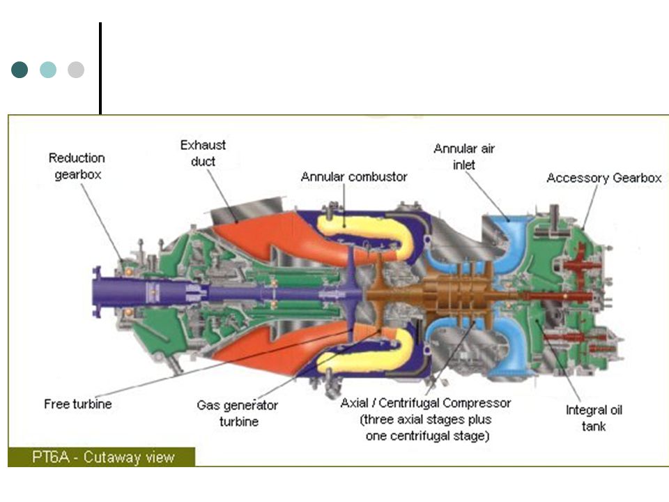
Revendo conceitos.... Turbina a gás (mostrada ao lado) tem um compressor para comprimir o gás succionado (usualmente ar); um combustor (ou queimador) para adicionar ‘energia’ ao ar pressurizado; e uma turbina para extrair energia proveniente do gás aquecido. A turbina a gás é uma máquina de combustão interna que utiliza processo de combustão contínua. Isto difere do motor a pistão onde a combustão é intermitente. Figura 1: Diagrama esquemático A) motor a jato aeronáutico; B) uma turbina a gás (para uso em terra e em turbohélice)
 tem um compressor para comprimir o gás succionado (usualmente ar); um combustor (ou queimador) para adicionar ‘energia’ ao ar pressurizado; e uma turbina para extrair energia proveniente do gás aquecido. A turbina a gás é uma máquina de combustão interna que utiliza processo de combustão contínua. Isto difere do motor a pistão onde a combustão é intermitente. Figura 1: Diagrama esquemático A) motor a jato aeronáutico; B) uma turbina a gás (para uso em terra e em turbohélice)")
5
Figura 2a. Diagrama volume-pressão do ciclo Brayton para uma unidade de massa de fluido de trabalho (ar, por exemplo) mostrando entradas e saídas de trabalho (W) e calor (Q). Figura 2b. Esquema da turbina mostrando pontos relativos ao ciclo Brayton do diagrama da Figura 2a.

6
THERMODINAMICA: CICLO BRAYTON

9
Acesse para baixar os arquivos de aulas ftp://161.24.15.247/Cristiane/

10
CÓDIGOS E PADRÕES

11
• Fornecem orientações de projeto e definições:
CÓDIGOS, POR QUÊ?: • Fornecem orientações de projeto e definições: Exemplo: Vibrações, Materiais, Conexões • Facilitar a construção e aquisição • Nenhum Código ‘projeta’ uma turbina a gás • São de natureza geral, qualquer particularidade pode exigir modificações

12
Códigos relevantes

13
Códigos comuns para aplicação em Oil & Gas
API Gas Turbines API 617 – Compressors API 614 – Lube Oil System API 670 – Machinery Protection API 613 – Load and Accessory Gear API 677 – Accessory Drive Gear API 671 – Flexible Couplings NFPA 70 Electric Code ASME PTC-22 Gas Turbine Testing ASME PTC-10 Compressor Testing ASME B133 - Gas Turbines

14
outros códigos internacionais
ISO Codes (ISO Gas Turbines) IEC/CENELEC (Electrical and Fire Systems) Local Government Codes EU Environmental and Health Compliance User Specific Specifications: – Upstream: Mostly API/firm – Midstream: Some API/flexible – Downstream: Mostly API/very firm
 IEC/CENELEC (Electrical and Fire Systems) Local Government Codes. EU Environmental and Health Compliance. User Specific Specifications: – Upstream: Mostly API/firm. – Midstream: Some API/flexible. – Downstream: Mostly API/very firm.")
15
API? American Petroleum Institute
US Petroleum Industry Primary Trade Association – 400 Member Companies – Covers all Aspects of Oil & Gas Industry – Accredited by ANSI (American National Standards Organization) – Started Developing Standards in 1924 – Maintains about 500 Standards – API Codes are Widely Referenced by EPA, OSHA, OPS, MMS, BLM, and Many Local Codes
 – Started Developing Standards in – Maintains about 500 Standards. – API Codes are Widely Referenced by EPA, OSHA, OPS, MMS, BLM, and Many Local Codes.")
16
API - Filosofia – Melhora na segurança
– Melhora de desempenho ambiental – Reduzir custos de engenharia – Melhora de intercâmbio entre equipamentos – Melhora na qualidade do produto – Menor custo de equipamento – Allows for Exceptions for Reason

17
API Standards com propósito de compra
Fornece meios para comprador normalizar as cotações obrigando os vendedores a cotar similares escopos. Fornecem linguagem comum e ajusta regras entre vendedor e comprador para reduzir desentendimento, por exemplo, define eficiência, procedimentos de testes, data sheets Claramente declara no início que Exceções são permitidas se conduzirem a melhora ou ofertas técnicas mais seguras

18
API Turbinas a gás no setor oil & gas, API 616 é a fundamental para quase todos especificações de compra • API 617 é utilizada para aplicações críticas de compressor centrífugo (alta pressão e alta energia) • NFPA 70 código elétrico para locais perigosos é exigência fundamental na API
 • NFPA 70 código elétrico para locais perigosos é exigência fundamental na API.")
19
API Standard Topics Definitions:
– ISO Rating, Normal Operating Point, Maximum Continuous Speed, Trip Speed, etc. Mechanical Integrity: – Blade Natural Frequencies, Vibration Levels, Balancing Requirements, Alarms and Shutdowns

20
API Standard Topics Design Requirements and Features:
– Materials, Welding, Accessories, Controls, Instrumentation, Inlet/Exhaust Systems, Fuel Systems Inspection, Testing, and Preparation for Shipment – Minimum Testing, Inspection and Certification Documentation Requirements Does not cover government codes & regulations

21
API API Data Sheets

22
API 616 Gas Turbine Note: API 616 does not apply to Aero-Derivative Gas Turbines – Only Industrial!

23
API 616 Intro & Definitions
1.0 Alternative Designs 1.1 Alternative designs allowed. Emphasized in API Foreword. 2.0 References 2.1 All reference standards are automatically included. All manufacturers take exception to this. 3.0 Definitions 3.17 ISO defined as T=15C, P= bar, RH=60% 3.19 Maximum allowable speed. Speed at which unit can safely operate continuously per manufacturer. 3.22 Maximum continuous speed: 105% highest design speed

24
API Definitions 3.26 Normal Operating Point: Usually the performance guarantee (heat rate, power) point for gas turbine. Defined by speed, fuel, and site conditions. 3.38 Rated speed: Power turbine speed at which site rated power is achieved. 3.42 Site rated conditions: Worst site condition at which still site rated power can be achieved. Provided by User. 3.45 Site rated power: The maximum power achievable at site rated conditions. Provided by Manufacturer. Note: Unless specifically stated by purchaser this is not a guarantee point.
 point for gas turbine. Defined by speed, fuel, and site conditions Rated speed: Power turbine speed at which site rated power is achieved Site rated conditions: Worst site condition at which still site rated power can be achieved. Provided by User Site rated power: The maximum power achievable at site rated conditions. Provided by Manufacturer. Note: Unless specifically stated by purchaser this is not a guarantee point.")
25
API Engine 3.50 Turbine trip speed: Speed where controls shut unit down. 3.51 Unit responsibility: Prime package contractor to user. 4.0 Basic Design 4.1.1 Equipment designed for 20 years and 3 years of uninterrupted service. Hot section inspection every 8000 hours. 4.1.2 Gas turbine vendor has unit responsibility unless otherwise specified. 4.1.5 Speed ranges: Two-shaft % rated speed, Single-shaft % rated speed.

26
API 616 - Engine 4.1.14 On-skid electric shall meet NFPA 70.
Most gas turbine internals shall be exchangeable at site. Disqualifies most aeroderivate gas turbines. Unit shall meet performance acceptance criteria both in the factory and at site. Most manufacturers take exception to site performance guarantee unless field test is performed. Vendor shall review customers installation drawings. Gas turbine must meet site rated power with no negative tolerances.

27
API Engine 4.2.1 Casing hoop stresses must meet ASME Section VIII. 4.2.7 Openings for borescope inspection must be provided for entire rotor without disassembly. 4.2.9 Field balancing (if required) without removal of casing is OK. 4.3.1 Combustors must have two igniters or igniter and cross-tubes. 4.3.2 Requires temperature sensors in each combustor. Not feasible in most gas turbine designs. T5 (2-shaft) or T6 (1-shaft) normal. 4.3.7 Fuel Wobbe index range must be indicated in proposal.
 without removal of casing is OK Combustors must have two igniters or igniter and cross-tubes Requires temperature sensors in each combustor. Not feasible in most gas turbine designs. T5 (2-shaft) or T6 (1-shaft) normal Fuel Wobbe index range must be indicated in proposal.")
28
The combustor casing is welded form solid machined and formed sheet titanium(!) components. What’s shown here is one of the spark plugs with the pilot burner fuel fitting and the fuel drain port in the lower right of the picture

29
The fuel manifold supplies diesel or kerosine to the twelve vaporiser sticks. To provide equal fuel quantities to all sticks, the fuel has to pass calibrated resirictor plates in each of the injectors

30
Except for the swirl vanes around the fuel nozzle on the top this combustor consists completely of sheet metal.

31
Índice de Wobbe Wobbe desenvolveu seu índice em 1926 ao estudar o fenômeno da combustão de gases injetados através de um orifício. Este índice se relaciona ao fluxo de energia térmica supondo-se inalteradas as condições de pressão de suprimento do gás e o diâmetro do orifício através do qual o gás flui.

32
Índice de Wobbe O índice de Wobbe decorre da seguinte equação:
Taxa de energia térmica (kcal/s) = poder calorífico do gás (kcal/Nm3) x vazão volumétrica do gás (Nm3/s) Q = taxa de energia térmica; DHgás = poder calorífico do gás; A = área da seção transversal do orifício de gás no queimador; k = coeficiente de descarga do orifício; Dp = pressão manométrica de suprimento do gás; r = massa específica do gás.
 = poder calorífico do gás (kcal/Nm3) x vazão volumétrica do gás (Nm3/s) Q = taxa de energia térmica; DHgás = poder calorífico do gás; A = área da seção transversal do orifício de gás no queimador; k = coeficiente de descarga do orifício; Dp = pressão manométrica de suprimento do gás; r = massa específica do gás.")
33
Índice de Wobbe A fórmula pode ser escrita como:
rar = massa específica do ar; d = densidade do gás combustível em relação ao ar.

34
Índice de Wobbe Wobbe definiu seu índice como: de tal maneira que
Vê-se claramente que dois gases diferentes produzirão no mesmo queimador, com a mesma pressão manométrica, a mesma taxa de energia térmica se os índices de Wobbe forem os mesmos.

35
Índice de Wobbe Um dos critérios adotados para que dois gases sejam intercambiáveis é que seus índices de Wobbe sejam aproximadamente os mesmos, dentro de um intervalo de 5%. Assim, para conseguir um índice de Wobbe adequado, utilizam-se misturas de gases na substituição. Como exemplo, citamos uma mistura de gás natural e ar para queimar em equipamento ajustado para gás de coqueria.

36
API Engine 4.4 Casing Connections: Section outlines good design practices. Most manufacturers are OK. Shafts shall be single piece heat treated steel. Stacked rotors with a tie-bolt are not allowed. Difficult to meet for most manufacturers and not critical if rotor has been operationally proven. Rotor shall be designed for overspeed up to 110% of trip speed. All rotor components must withstand instantaneous loss of 100% shaft load (e.g. coupling failure). 4.6 Seals: Renewable seals at all close clearance points
. 4.6 Seals: Renewable seals at all close clearance points.")
37
turbine rotor

38
rotor components

39
Figura 2.8 – Ilustração do diâmetro inducer e exducer nos rotores do compressor e turbina

41
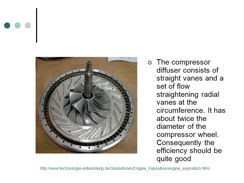
The compressor diffuser consists of straight vanes and a set of flow straightening radial vanes at the circumference. It has about twice the diameter of the compressor wheel. Consequently the efficiency should be quite good
42
compressor cover/bearing housing assembly
compressor cover/bearing housing assembly. This is one of the most complicated parts of the whole turbine engine because it contains the complete lubrication system for the single hydrodynamic and the two hybrid ball bearings.

43
Bearing-housing

44
Notice the cute airfoil shape of the vanes
Notice the cute airfoil shape of the vanes. This is the maximum exhaust flow - minimum charge pressure - position.

45
API Engine 4.7 Rotordynamics: Follow good design practices for progressive balancing with residual unbalance check. High speed balancing is discouraged. Hydrodynamic radial and thrust bearings are preferred. Thrust- Tilt pad, Radial Tilt pad or sleeve. If rolling element bearings are used they must meet 50,000 hours of continuous operation. Bearings: Labyrinth type seal required. Lip seal not acceptable. Two radial proximity probes in radial bearings and two axial proximity probes in thrust bearings.

46
Mapa do compressor O mapa do compressor descreve as características particulares de desempenho de um compressor, incluindo a eficiência, vazão, a capacidade de aumentar a pressão e a rotação

47
Mapa do compressor

48
A relação de pressão é definida como a divisão entre a pressão de saída do compressor pela pressão na sua entrada, ambas em condição absoluta.

49
Mapa do compressor - Linha de Surge
Bombeamento (ou Surge, na língua inglesa) é o limite esquerdo do mapa do compressor. Operar à esquerda desta linha representa uma região de instabilidade. Esta região é caracterizada pela vibração suave e flutuação de pressão no compressor. A contínua operação nesta região pode levar a quebras prematuras de turbo-compressores devido às altas cargas axiais. O surge geralmente é esperado em condições onde o motor está em rotações baixas e a plena carga; assim pode ser um indício de que o tamanho do compressor é grande.
 é o limite esquerdo do mapa do compressor. Operar à esquerda desta linha representa uma região de instabilidade. Esta região é caracterizada pela vibração suave e flutuação de pressão no compressor. A contínua operação nesta região pode levar a quebras prematuras de turbo-compressores devido às altas cargas axiais. O surge geralmente é esperado em condições onde o motor está em rotações baixas e a plena carga; assim pode ser um indício de que o tamanho do compressor é grande.")
50
Mapa do compressor - Linha de Choke
A linha de estagnação (choke, na língua inglesa) é o limite à direita do mapa do compressor é o ponto de máxima vazão do rotor. A linha de choke é normalmente definida pelo ponto onde a eficiência do compressor se torna muito baixa. Além da rápida queda de rendimento do compressor para além deste ponto, a relação de compressão é muito baixa.
 é o limite à direita do mapa do compressor é o ponto de máxima vazão do rotor. A linha de choke é normalmente definida pelo ponto onde a eficiência do compressor se torna muito baixa. Além da rápida queda de rendimento do compressor para além deste ponto, a relação de compressão é muito baixa.")
51
Mapa do compressor - Ilhas de eficiência
As ilhas de eficiência são regiões concêntricas nos mapas que representam a eficiência do compressor em qualquer ponto no mapa. A ilha menor perto do centro do mapa é a ilha de maior eficiência

52
API 616 - Engine 4.9.2 Synthetic lube oil is OK.
4.9.5 Integrated or separate lube GT / Compressor oil system OK. 4.9.7 Lube oil system must meet API 614. Note: Lube oil tank typically integrated into skid. 4.10 Materials: Follow good design rules. Purchaser may require 100% radiography magnetic particle inspection, or liquid penetrant inspection on all welds. A SS nameplate to include rated performance and conditions, critical speeds, maximum continuous speed, overspeed trip, and fuel type.

53
API 616 - Accessories 5.0 Accessories
Electric, pneumatic, electro-hydraulic, gas engine, steam turbine all acceptable starter/helper motors. Starter drivers are uncoupled after startup, helper drivers remain coupled. Starter motors must be supplied with all necessary gears, couplings, and clutches. Starters shall be rated 110% of starting torque required. Vendor to supply torque curves. 5.1.3 Turning gear: Device to periodically rotate to avoid shaft deformation. Generally not required on smaller turbines

54
API 616- Accessories 5.2.1 Vendor to supply accessory gear for starting, auxiliary equipment (LO pump). Vendor to also supply separate load gear if required. All gears shall meet API 613. Accessory gears shall be rated for 110% of required load. 5.2.2 Vendor to supply all couplings and guards for load and accessory shafts. Couplings to be sized for maximum continuous torque and meet API 671. 5.3 Gas turbine to be supplied on single mounting plate (baseplate). Typically interpreted to allow for skid mounting. Skid to be designed to limit worst case shaft alignment change to 50 micrometers. 5.3.2 Single piece baseplate preferred. Baseplate shall extend under driven equipment.
. Vendor to also supply separate load gear if required. All gears shall meet API 613. Accessory gears shall be rated for 110% of required load Vendor to supply all couplings and guards for load and accessory shafts. Couplings to be sized for maximum continuous torque and meet API Gas turbine to be supplied on single mounting plate (baseplate). Typically interpreted to allow for skid mounting. Skid to be designed to limit worst case shaft alignment change to 50 micrometers Single piece baseplate preferred. Baseplate shall extend under driven equipment.")
55
API 616 – Accessories/Controls
Skid to permit field leveling. Controls and instrumentation shall be suitable for outdoor installation. Usually not necessary or practical. GT instruments and controls shall meet API 670. GT control system must provide for safe startup, operation, and shutdown of gas turbine. Unit shall continue to operate for specified time after AC failure. To overcome delay of emergency power startup. Automatic start to require only single operator action

56
API 616 – Controls Control system to completely purge unit prior to startup. Load control to limit driven equipment speed to 105% rated speed. Alarm/shutdown system to be provided to protect unit and operator. Both Normal and Emergency (Fast) shutdown (i.e., cut of of fuel supply) must be available. Fuel control must include separate shutoff and vent valves, separate from fuel control valve, with local and remote trip. Alarm and shutdown switches shall be separate. Often not practical (e.g., flame detector, axial thrust position
 shutdown (i.e., cut of of fuel supply) must be available Fuel control must include separate shutoff and vent valves, separate from fuel control valve, with local and remote trip Alarm and shutdown switches shall be separate. Often not practical (e.g., flame detector, axial thrust position.")
57
API Alarms a - Optional

58
API Sensors Alarm and trip settings not adjustable from outside housing. Not relevant with modern control systems. All instruments (other than shutdown switches) shall be replaceable without shutting unit down. Not practical on many switches. Off-skid or on-skid control system to be supplied with unit. Any on-skid control system must meet hazardous area requirements (NFPA70). On-skid electric systems must meet NFPA 70.
 shall be replaceable without shutting unit down. Not practical on many switches Off-skid or on-skid control system to be supplied with unit Any on-skid control system must meet hazardous area requirements (NFPA70) On-skid electric systems must meet NFPA 70.")
59
API 616 – Inlet/Exhaust 5.4.7 Instrumentation: The API 616 Data Sheets Must be Filled Out by Purchaser to Indicate the Required Instrumentation. Manufacturer will often cross out line to indicate noncompliance.Vendor must include in proposal full list of instrumentation. API 670 governs basic requirements for temperature and vibration sensors. Air inlet and exhaust system including inlet filter, inlet/exhaust silencers, ducting, and joints to be provided by vendor. Inlet system shall be designed for maximum 4 in H2O pressure drop at site rated power. Inlet/exhaust system design life is 20 years.

60
API Anciliaries Bolts, rivets or fasteners are not permitted in inlet system. A gas turbine compressor cleaning system must be provided. Inlet Filter System requires walkways and handrails. Not necessary for very small units. 5.5.5 Inlet/Exhaust Silencer: Internals to be Stainless Steel. External Carbon Steel. 5.7.3 Unit must be supplied with gas detection system, fire detection system, and fire suppression system to meet NFPA. Fire suppression shall be automatic based on thermal detection. Typical: Thermal, thermal gradient, LEL, and flash detector. CO2 for suppression.

61
API 616 – Enclosure/Fuels 5.7.5 When enclosure is supplied it must be weatherproof and include fire detection/suppression, ventilation/purging, lights, and doors, and windows. Gas fuel system: Must include strainer, instrumentation, manifolds, nozzles, control valve, shutoff valve, pressure regulator, and vent valve. Fuel gas piping must be stainless steel. Liquid fuel system: Must include pump, atomizing air, two shutoff valves, instrumentation, control valves, flow dividers, nozzles, and manifolds. Newer systems employ variable speed pumps instead of control valves.

62
API Fuels If dual fuel system is provided it must allow bumpless bidirectional transfer. Vendor must review customer’s fuel supply system. Heating value of fuel cannot vary by more than ±10%. Purchaser must specify required site emissions levels for NOx, CO, UHC, et al. 6.0 Inspection, Testing, and Preparation for Shipment Inspections: Standard machinery type includes, materials, mechanical, Radiographic, ultrasonic, magnetic particle, dye penetrant, etc.

63
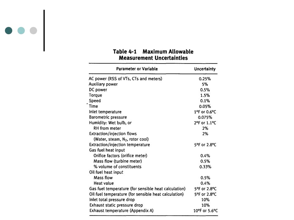
API Testing Hydrostatic tests: Vessels and piping per ASME Section VIII (1.5 times rated pressure). 6.3.3 Mechanical Running Test: 4 hour no load full speed (maximum continuous speed) test to verify that the complete gas turbine package (including all auxiliaries except for inlet/exhaust system) operates within vibration and operational control limits. Contract coupling should be used. Rotordynamic signature and vibrations must be recorded. Compliance with these requirements is critical. 6.3.4 Optional Tests (These tests are not optional if purchaser marks them in the API 616 data sheets)
 test to verify that the complete gas turbine package (including all auxiliaries except for inlet/exhaust system) operates within vibration and operational control limits. Contract coupling should be used. Rotordynamic signature and vibrations must be recorded. Compliance with these requirements is critical Optional Tests (These tests are not optional if purchaser marks them in the API 616 data sheets)")
64
API Testing Optional Performance Test: Unit full load tested to PTC 22. Optional Complete Unit Test: Similar to Mechanical run test but to include driven equipment. Gear must be tested with unit during mechanical run test. Other optional test: Sound level, Auxiliary Equipment, Fire Protection, Control response, Spare Parts. If unit fail mechanical run test, complete disassembly is required.

65
API 616 – Vendor Data 6.4 Preparation for Shipment: Short term – plastic wrapping. Long Term – crating, surface anti-corrosion treatment, nitrogen fill of all vessels. 7.0 Vendor’s Data: Strictly follows Data Sheet requirements. Manufacturers must cross out line if they do not meet API. Minimum must contain performance maps, performance calculations, mechanical, hydraulic, layout, and electrical drawings, P&IDs, test and inspection results, as-built, parts lists, operation and maintenance manuals, installation manual, and technical data.

66
API 616 – Vendor Data

Apresentações semelhantes