Carregar apresentação
A apresentação está carregando. Por favor, espere


1
Electrónica Simbologia

2
Unidades SI Unidades SI de base Unidades SI derivadas Quantidade
Símbolo Comprimento metro m Massa kilograma kg Tempo segundo s Corrente eléctrica ampére A Temperatura kelvin K Quantidade de substância mole mol Intensidade luminosa candela cd Quantidade Unidade Símbolo Angulo plano radiano rad Angulo sólido esteradiano sr Temperatura Celsius grau celsius ºC Capacitância farad F C/V Carga eléctrica coulomb C A.s Condutância eléctrica siemen S A/V Indutância eléctrica henry H Wb/A Potencial eléctrico (tensão) volt V W/A Resistência eléctrica ohm W V/A Energia joule J N.m Força newton N kg.m/s2 Frequência hertz Hz 1/s Luminância lux lx lm/m2 Fluxo luminoso lúmen lm cd.sr Fluxo magnético weber Wb V.s Densidade de fluxo magnético tesla T Wb/m2 Potência watt J/s Pressão pascal Pa N/m2
 volt. V. W/A. Resistência eléctrica. ohm. W. V/A. Energia. joule. J. N.m. Força. newton. N. kg.m/s2. Frequência. hertz. Hz. 1/s. Luminância. lux. lx. lm/m2. Fluxo luminoso. lúmen. lm. cd.sr. Fluxo magnético. weber. Wb. V.s. Densidade de fluxo magnético. tesla. T. Wb/m2. Potência. watt. J/s. Pressão. pascal. Pa. N/m2.")
4
prefixos SI

6
Componentes básicos

7
Componentes Electrónica
Analógica baixa potência potência Digital

8
Resistências R

9
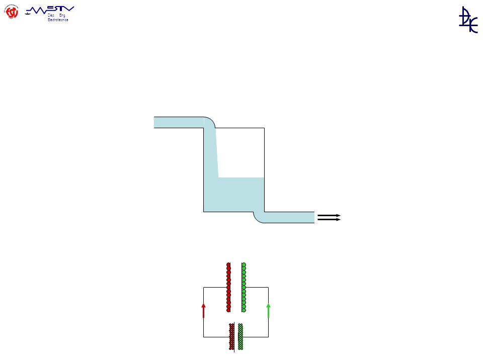
Bobines / Condensadores
L + + +

10
Transformadores T

11
Referências (Terras / Massas)
IDC + – 20 V V+ – V– = 20V 20V 0V 20V 30V 10V 20V 15V -5V 20V 10V

12
Resistências não lineares
NTC PTC LDR

13
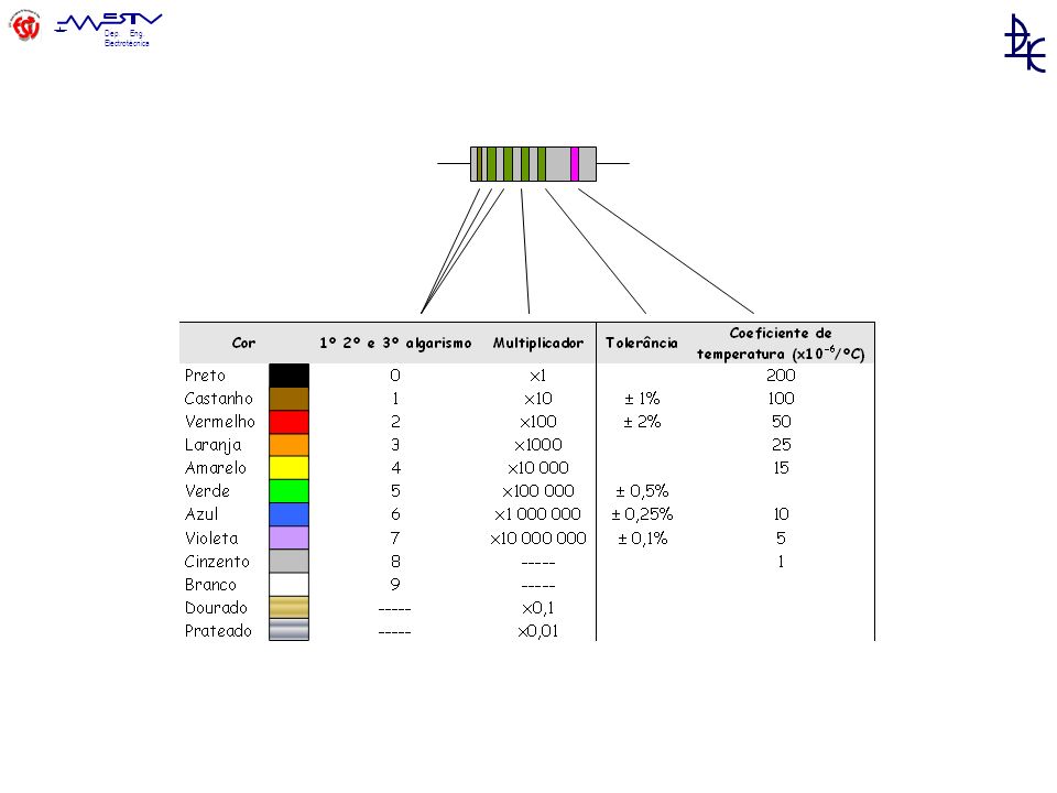
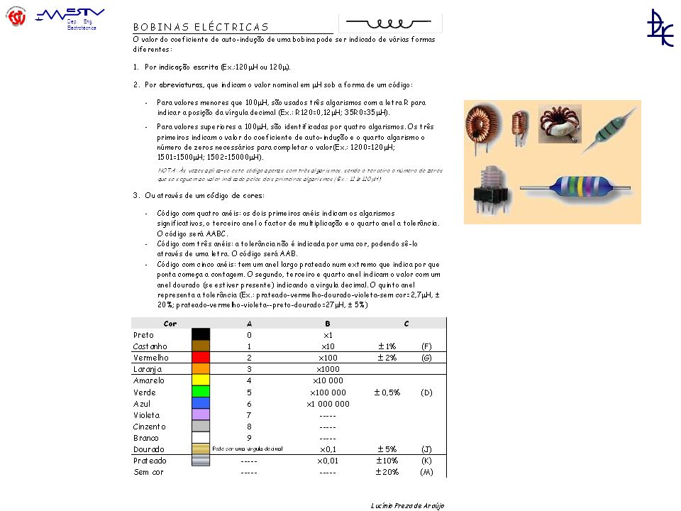
Resistências - códigos

15
Codificação de : Digítos Multiplicador Tolerância
Coeficiente temperatura em: 4, 5 ou 6 faixas de cor. 5% Standard Values Decade multiples are available from 10 W through 22 MW 10 11 12 13 15 16 18 20 22 24 27 30 33 36 39 43 47 51 56 62 68 75 82 91 10% Standard Values Decade multiples are available from 10 W through 1 MW 10 12 15 18 22 27 33 39 47 56 68 82 100, 110, 120, 130, 150, 160, 180, 200, 220, 240, 270, 300, 330, 360, 390, 430, 470, 510, 560, 620, 680, 750, 820, 910, ( )
")
16
Nota: O valor obtido vem expresso em Ohm (). (
Nota: O valor obtido vem expresso em Ohm () (*) 3º anel dourado → R <10Ω ; 3º anel prateado → R <1Ω
 (*) 3º anel dourado → R <10Ω ; 3º anel prateado → R <1Ω.")
18
Tolerância Castanho 1 Preto 0 Dourado 5% 9,5 W 10 x 100 5% 10 W 5%
10,5

19
R33 0,33 W 34R2 34,2 W 47k 47 kW 2M1 2,1 MW

20
SMT Normais Precisão Codificação: 3 dígitos 4 dígitos
1º/2º - dígitos significativos 3º dígito – potência de 10 ou R – ponto decimal (R < 10 Ohms) 1º/2º/3º - dígitos significativos 4º dígito – potência de 10 ou R – ponto decimal (R < 10 Ohms) Exemplos: "334" = 33 × 10,000 ohms = 330 kiloohms "222" = 22 × 100 ohms = 2.2 kiloohms "473" = 47 × 1,000 ohms = 47 kiloohms "105" = 10 × 100,000 ohms = 1 megaohm "100" = 10 × 1 ohm = 10 ohms (também possível serem marcadas como “10”) "220" = 22 × 1 ohm = 22 ohms ( “ “ “ “22”) "4R7" = 4.7 ohms "0R22" = 0.22 ohms "0R01" = 0.01 ohms "1001" = 100 × 10 ohms = 1 kiloohm "4992" = 499 × 100 ohms = 49.9 kiloohm "1000" = 100 × 1 ohm = 100 ohms
 1º/2º/3º - dígitos significativos. 4º dígito – potência de 10. ou. R – ponto decimal (R < 10 Ohms) Exemplos: 334 = 33 × 10,000 ohms = 330 kiloohms. 222 = 22 × 100 ohms = 2.2 kiloohms. 473 = 47 × 1,000 ohms = 47 kiloohms. 105 = 10 × 100,000 ohms = 1 megaohm. 100 = 10 × 1 ohm = 10 ohms (também possível serem marcadas como 10 ) 220 = 22 × 1 ohm = 22 ohms ( 22 ) 4R7 = 4.7 ohms. 0R22 = 0.22 ohms. 0R01 = 0.01 ohms = 100 × 10 ohms = 1 kiloohm = 499 × 100 ohms = 49.9 kiloohm = 100 × 1 ohm = 100 ohms.")
21
Potência

23
Condensadores

25
Tântalo Polipropileno Poliéster Electrolítico Cerâmico

26
1. Disc Ceramic: While they are limited to quite small values, disc cermaics boast a small and solid construction with comparatively high voltage ratings. They range from 1pF to 0.47µF and are not polarised. This type can often be used to replace a polyester capacitor of the same value. 2. Polyester "Green Caps": Ranging from 0.01µF to 5µF polyester capacitors have similar properties to disc ceramics with some larger values and a slightly larger construction. They are not polarised. 3. MKT Polyester: A varation of polyester capacitors used where price matters less than performance. High temperature stability and accuracy land MKT capacitors in higher end audio circuits and power supplies. They range from 1nF to about 10µF. (values over 1µF are quite expensive) MKTs are not polarised. 4. Tantalum: Tantalum capacitors pack a large capacity into a relatively small and tough package compared to electrolytics, but pay for this in voltage ratings. The device pictured above is 100µF (like the electrolytic next to it) but is rated at 3.6V, compared to 16V. They are often polarised and range from 0.1µF to 100µF. 5. Radial Electrolytic: Used for all values above 0.1µF. Electrolytics have lower accuracy and temperature stability than most other types and are almost always polarised. It's usually best to only use an electrolytic when no other type can be used, or for all values over 100µF. Cheap electrolytics are usually made from plastic and rubber and therefore melt easily during soldering. 6. Axial Electrolytic: The same as other electrolytics but the leads emerge from each end, rather than the same end as in the radial types.
 MKTs are not polarised. 4. Tantalum: Tantalum capacitors pack a large capacity into a relatively small and tough package compared to electrolytics, but pay for this in voltage ratings. The device pictured above is 100µF (like the electrolytic next to it) but is rated at 3.6V, compared to 16V. They are often polarised and range from 0.1µF to 100µF. 5. Radial Electrolytic: Used for all values above 0.1µF. Electrolytics have lower accuracy and temperature stability. than most other types and are almost always polarised. It s usually best to only use an electrolytic when no other type. can be used, or for all values over 100µF. Cheap electrolytics are usually made from plastic and rubber and therefore. melt easily during soldering. 6. Axial Electrolytic: The same as other electrolytics but the leads emerge from each end, rather than the same end. as in the radial types.")
27
Condensadores – série de valores básicos 10 12 15 18 22 27 33 39 47 56
Base = pico Farads (pF) 10 12 15 18 22 27 33 39 47 56 68 82 2,2pF, 22pF, 220pF, 2,2nF, 22nF, 220nF, 2,2uF, 22uF, 220uF, 2200uF 1pF, 10pF, 100pF, 1nF, 10nF, 100nF, 1uF, 10uF, 100uF, 1000uF
 ,2pF, 22pF, 220pF, 2,2nF, 22nF, 220nF, 2,2uF, 22uF, 220uF, 2200uF. 1pF, 10pF, 100pF, 1nF, 10nF, 100nF, 1uF, 10uF, 100uF, 1000uF.")
28
Código cores 1% 2% 2,5% 5% 33000 pF, 10%, 250V
Base = pico Farads (pF) 1% 2% 2,5% 5% 33000 pF, 10%, 250V
 1% 2% 2,5% 5% pF, 10%, 250V.")
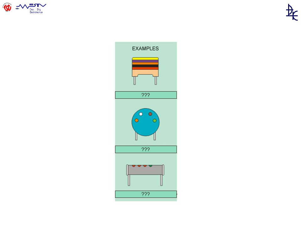
29
??? ??? ???
30
Código alfanumérico 103 M 10 K J 1º e 2º algarismo multiplicador
tolerância 103 M pF = 10 nF 20% 10 pF – 3º algarismo = 9 (ex: 479 = 47 / 10 = 4,7 pF) K 10 K J 10 x 1000 = pF = 10 nF 5% 10 pF 10 pF B 0,1 pF F 1% M 20% C 0,25 pF G 2% P +100% – 0% D 0,5 pF H 3% S +50% – 20% 1 pF J 5% Z +80% – 20% ou +100% – 20% 2 pF K 10%
 K. 10 K. J. 10 x 1000 = pF = 10 nF 5% 10 pF. 10 pF. B. 0,1 pF. F. 1% M. 20% C. 0,25 pF. G. 2% P. +100% – 0% D. 0,5 pF. H. 3% S. +50% – 20% 1 pF. J. 5% Z. +80% – 20% ou +100% – 20% 2 pF. K. 10%")
31
Condensadores electrolíticos - tântalo
100 uF, 20 V Tântalo Rosa 35V

32
Condensadores electrolíticos - alumínio
Óxido de Alumínio axial radial

33
Condensadores electrolíticos - tântalo

35
Osciladores Xtal “555”

36
Díodos K A A K + Porquê ? + Zener LED Fotodíodo

37
Região de resistência negativa
Schottky (VF menor, comutação mais rápida) Região de resistência negativa Tunel
 Região de resistência negativa. Tunel.")
38
+ + -

39
Transístores + – + – C E B NPN i PNP NPN PNP

40
Transistor, Metal-Oxide, Single-Gate
Field Effect Transistor (Efeito de Campo eléctrico) D G S Drain Source Gate v FET – canal N FET – canal P Metal Oxid Semiconductor FET Transistor, Metal-Oxide, Single-Gate
 D. G. S. Drain. Source. Gate. v. FET – canal N. FET – canal P. Metal Oxid Semiconductor FET. Transistor, Metal-Oxide, Single-Gate.")
41
Norma europeia BC337

42
Norma americana 2N222

43
Electrónica de potência

44
IGBT Tirístor DIAC TRIAC Power MOSFET
(SCR – Silicon Controled Rectifier) DIAC TRIAC Power MOSFET
 DIAC. TRIAC. Power MOSFET.")
47
entradas saídas Reset VCC R/W D2 D3 D4 D5 YYxxx 1 22 3 10 11 12 13

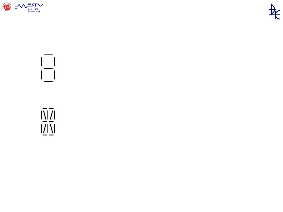
49
Diagramas temporais

50
Instrumentos de medição

51
V R A R W Wh W cosf f

52
Aparelhos de alimentação

53
Fonte alimentação: - dupla (+/gnd/-) - corrente excessiva Amperímetro: - directo à saída de uma fonte !

54
Componentes de instrumentação

55
Indutivo Capacitivo Óptico

56
A D D A DAC ADC

57
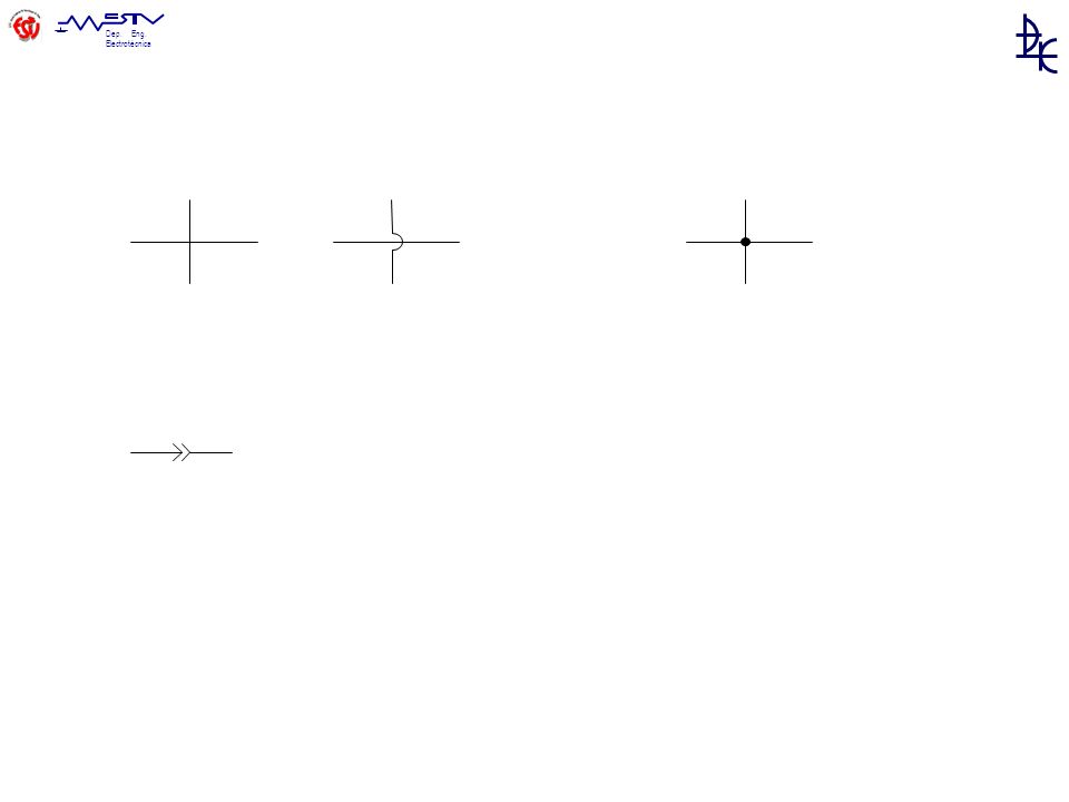
Ligações e fios

59
120 V, 60 Hz 230 V, 50 Hz 180º 360º 0º D Y Z M M M

60
AVISOS

61
IEC Symbol 5036 ISO 3864, electrical hazard.
Many products now come under European Directives and to be able to sell them within the EU some must bear the CE mark as a legal requirement. This mark is the manufacturers claim that the product meets all of the relevant European Directives. The VDE Testing Institute as founded in 1920 in Berlin and relocated to Offenbach am Main in 1968 where it has gained worldwide importance. The VDE Testing and Certification Institute is accredited on a national and international level for the testing and certification of electro technical equipment, components and systems. Testing of electro technical products is conducted mainly for safety and electromagnetic compatibility. IEC Symbol 5036 ISO 3864, electrical hazard.

62
Modelo europeu Choque eléctrico precaução ESD radioactividade ionização laser tóxico Inflamável irritante corrosão Risco de explosão Sem risco de explosão

63
Classes de isolamento Class 0 – Sem protecção (utilização em locais secos). Um defeito provoca um choque eléctrico. Proíbido em alguns países Class I – Chassis ligado à terra. Um defeito provoca uma fuga para o condutor de terra (normal/ com diferencial) Class II – isolamento duplo – evita necessidade de ligação à terra (não há ligação entre partes eléctricas e as zonas de manipulação) Class III – equipamentos alimentados por SELV (Safety Extra Low Voltage). A tensão de alimentação é reduzida, de forma a que não haja perigo, mesmo com contacto. IEC 417 No. 5019 IEC 417 No. 5172
 Class II – isolamento duplo – evita necessidade de ligação à terra (não há ligação. entre partes eléctricas e as zonas de manipulação) Class III – equipamentos alimentados por SELV (Safety Extra Low Voltage). A tensão de alimentação é reduzida, de forma a que não haja perigo, mesmo com contacto. IEC 417 No IEC 417 No")
64
AWG American Wire Gauge

Apresentações semelhantes


>")


